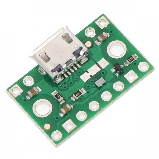
Product description: microUSB power connector with FPF1320 multiplexer
The module allows you to select the power source of the target circuit from thetwo connected input lines. The power supply should be connected to the microUSB connector or the VINA and VINB goldpin pins. The output voltage is obtained from the goldpin outlet marked with the VOUT symbol. The source can be switchedautomatically, when one is disconnected, the second is switched on using the digital signal given on the SEL pin on by theuser.
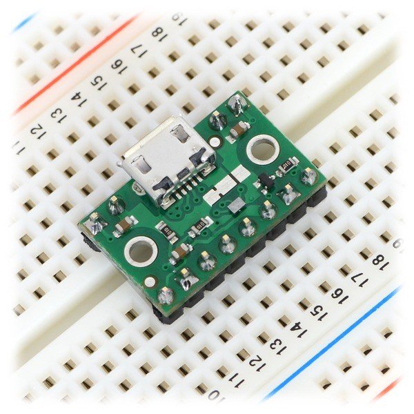
Power connector microUSB with multiplexer FPF1320 connected to the breadboard.
The system is operated as a traditionalmultiplexerusing digital signals. It allows you to connect a voltage in the rangefrom 1.5 V to 5.5 Vthe flow of currentup to 1.5 A. The driver is based on MOSFET transistors that allows to avoid large voltage drops. There is also protection from the current reverse.
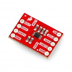
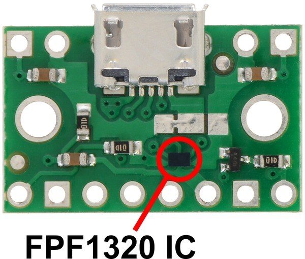
Closeup on the multiplex FPF1320 IC.
Circuit FPF1320 is produced in a small, difficult for self-soldering case BGA. The board allows you to gain access to its inputs through traditionalgoldpin connectors- raster 2.54 mm. Due to this, the module can be mounted directly onthe breadboard or plug withwires. Board sizes12.7 x 20.3 mm).
Inputs
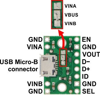
Insights power connector microUSB with multiplekserem FPF1320.
| PIN | Description |
| VINA | The input of power bus A. Allows you to connect the voltage range from 1.5 V to 5.5 V. |
| VINB | The input of power bus B. Allows you to connect the voltage range from 1.5 V to 5.5 V. By default connected to the power line of microUSB connector via the jumper on the board. |
| VBUS | 5 V voltage from the connector microUSB. By default, connected to the power bus B (VINB) using the jumper on the board. |
| VOUT | Output voltage. |
| GND | The ground of the system. All pins marked with this symbol are connected (also with the ground of the microUSB connector). |
| SEL |
Input power supply:
On the board there are pull-up resistors, making the default bus B (VINB). |
| EN |
The input connected to the low state low will disable the output VOUT. On the board there are pull-up resistors, making a default layout turn on. |
| D− D+ ID |
Output USB interface:
|
Module support
The input voltages should be fed to bus A (VINA) and B (VINB) terminals, which are connected to the microUSB connector. The choice of which source will be on the output is done by entering the logic state on the SEL output
- low state (<0.65 V) results in connection of the output with bus A (VINA),
- high state (> 1.15 V) results in connection of the output to bus B (VINB).
The PCB has pull-up resistors connected to the VINB input, which makes the B (VINB) bus selected by default. In the case when no voltage appears on the B-rail, the module will automatically transfer the voltage from source A (VINA) to the output.
EN pinallows the VOUT output to be completely disconnected. Giving a low state to this output causes that there will be no voltage at the output. Regardless of what will be connected to bus A and B. On the board there is a pull-up resistor (100 kΩ), which makes the system switched on by default.
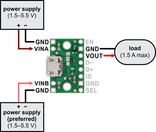
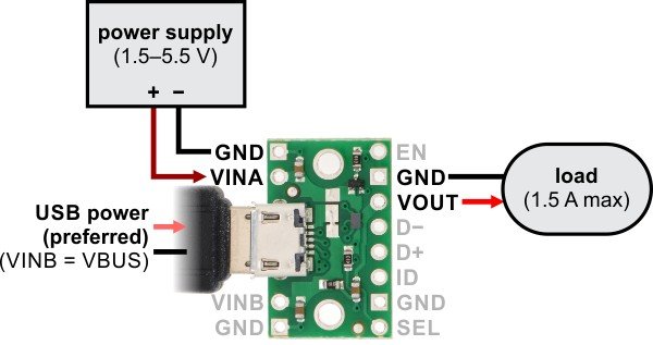
The system can also be connected so that the voltage switches in automatic mode:
-
Without USB cable
When connected, like in the drawingabove, the output will have voltage from bus B (VINB). After disconnecting power from bus B, the system will automatically switch to power supply from bus A (VINA).
-
USB cable as a primary source
The figure above shows the connection with the USB connector. In this case, the preferred voltage is from theUSB cable- connected to the bus B (VINB) via a jumper. After shutdown the system switches to bus A.
-
USB cable as an additional source
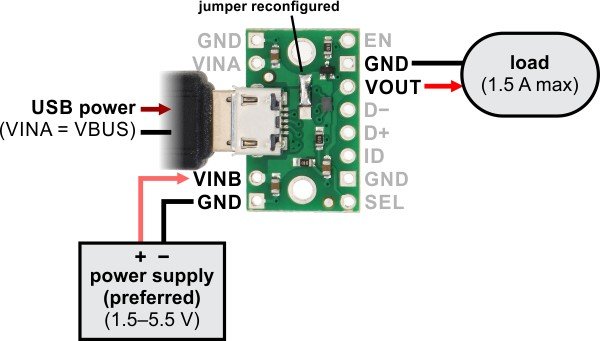
If the preferred voltage is to be from an external source, and a backup from a USB cable, the system should be connected as in the picture above. Remember to change the jumper on the board - connecting the USB connector with bus A.
Useful links |
