Description
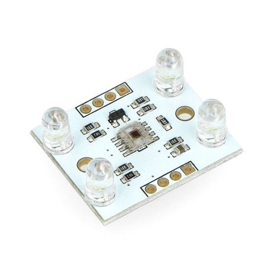
The module with TCS3200D sensor allows the measurement of the color (RGB - Red, Green, Blue), the output of which is frequency dependent on the intensity of light of the selected color. It is supported by any commissioning set with a microcontroller equipped with a counter, for example,STM32DiscoveryorArduino.
Specification
- Power supply voltage: 2.7 V to 5.5 V
- Programmable color selection
- Programmable output frequency:
- 500 - 600 kHz
- 100 - 120 kHz
- 10 - 12 kHz
- Error of non-linearity at the level of 0.2% at 50 kHz
- Pins: goldpin
- Simple connection with a microcontroller (frequency readings)
- Built-in 4 LEDs illuminating the studied object
- Dimensions: 32 x 25 mm
Details inthe documentation.
|
The product is compatible with Arduino Check how to connect the sensor to the Arduino inour guide. |
Service and output
The module is powered with the voltage in the range of 2.7 V to 5.5 V, thanks to it, it is reliable in the systems of 3.3 V and 5 V. The sensor can be connected to any commissioning set with a microcontroller that has a timer with the frequency input, for example,STM32DiscoveryorArduino.
The output is a signal with a frequency that depends on the light intensity of the color selected by the pins S2 and S3.
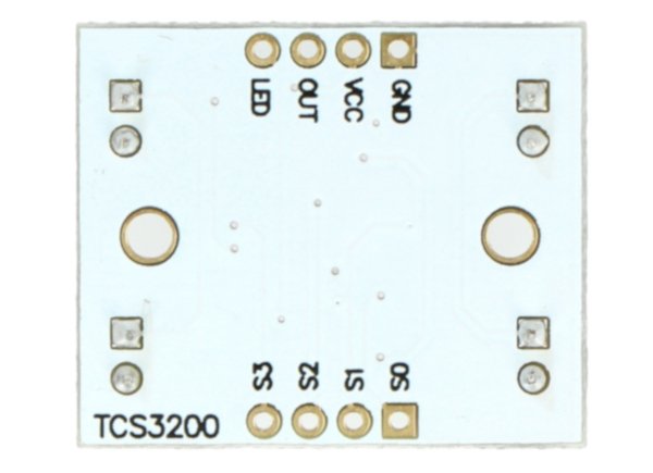
Detailed description of the pins is available in the arrays in the further part of the description. Pins are the popular goldpin connectors, allowing for the connection of the sensor with the main module using theconnecting cables.
Description of pins of the module with the sensor TCS320
|
Name |
Description |
|
VCC |
Supply voltage from 2.7 V to 5.5 V. |
|
GND |
The potential of the ground of the system. |
|
ŌĒ |
The activation of the frequency output OUT. The pin is put on by low status. |
|
OUT |
Frequency output. |
|
S0, S1 |
Inputs for scaling the output frequency. The description is below. |
|
S2, S3 |
Inputs to select the type of photodiode. The description is below. |
Module's pins with sensor TCS320.
Setting
Using the configuration inputsS0andS1, selected is prescaler (divider) of the output frequency signal thanks to which we can adjust the frequency range for the used microcontroller. InputsS2andS3are used to selectthe type of measuring photodiode: red, green, blue or clear options, that is without filtering (all RGB components will be measured simultaneously).
Selection of divider of the output frequency
|
S0 |
S1 |
Scale of output frequency |
|---|---|---|
|
L |
The sensor is disconnected | |
|
L |
H |
2 % 10-12 kHz |
|
H |
L |
20 % 100-120 kHz |
|
H |
H | 100 % 500-600 kHz |
Selecting the type of photodiode (of filtration)
|
S2 |
S3 |
Type of photodiode |
|---|---|---|
|
L |
L | red (R) |
|
L |
H | blue (B) |
|
H |
L | clear (RGB) (unfiltered) |
|
H |
H | green (G) |
L (Low) - low status
H (High) - high status
Useful links |


