Product description: Mini Maestro USB 12 channel servo controller - Pololu 1352
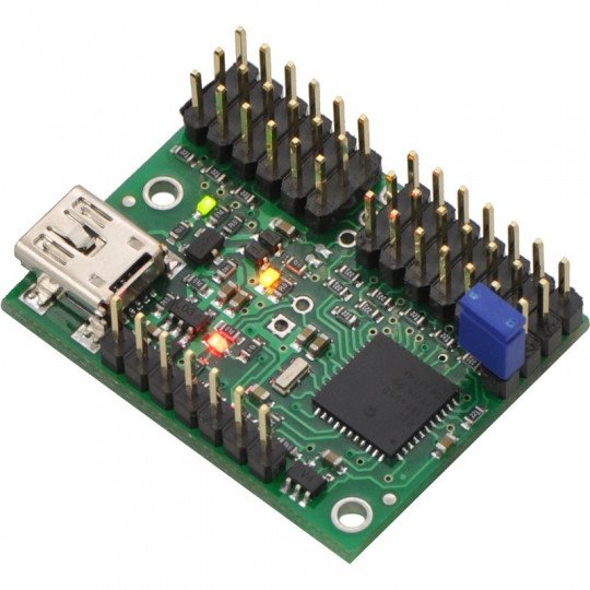
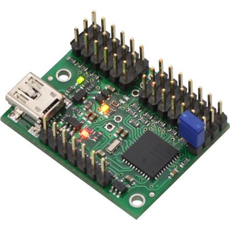
12-channel servo controller with support for digital and analog signals. The user can control servos via: PC application (USB), serial interface and simple scripting language.
|
The product is compatible with Arduino The manufacturer makes the library available on GitHub for Arduino users. |
Video
A video produced by Pololu showing the capabilities of the product.
Pololu Maestro controller description
The Maestro series are versatile servo controllers capable of also interpreting digital and analog signals. With a variety of control options, a wide range of supply voltages, and simple operation, the Maestro is suitable for many servo projects. Depending on the number of servos used, the user can choose the appropriate version. 6, 12, 18 and 24 channel modules are available.
|
|
||||
| Number of channels: | 6 | 12 | 18 | 24 |
| Number of analog inputs: | 6 | 12 | 12 | 12 |
| Number of digital inputs: | 0 | 0 | 6 | 12 |
| Width [mm]: | 21,6 | 27,9 | 27,9 | 27,9 |
| Length [mm]: | 30,5 | 36,1 | 45,7 | 58,4 |
| Weight [g]: | 3,0 | 4,2 | 4,9 | 6,0 |
| Pulse frequency: | 33-100 Hz | 1-333 Hz | 1-333 Hz | 1-333 Hz |
| Pulse range: | 64-3280 μs | 64-4080 μs | 64-4080 μs | 64-4080 μs |
| Script size: | 1 KB | 8 KB | 8 KB | 8 KB |
Controller support
The user can customize the controller to meet the needs of their project by choosing from three different communication interfaces:
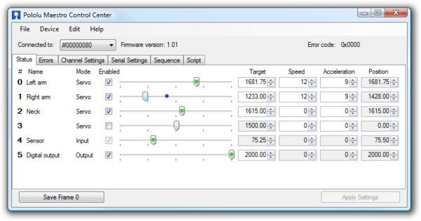
USB computer application - the device connects to the computer using a mini USB cable. An intuitive program is used to operate the controller, which allows, among others:
- controlling the position of the orb
- setting the speed of servorotation
- reading data from analogue and digital inputs
- setting the logical values at the I/O outputs
To use the USB control option, all you need to do is download the program to your hard drive (versions: Windows, Linux), run it, and connect the controller to any USB port on your computer.
Serial interface (UART) - the interface allows to connect Maestro to the central unit, which can be any microcontroller or runtime kit such as Arduino, STM32Discovery or Rasbperry Pi. Servos are operated by sending special character commands. Examples along with a description of commands can be found in the manual.
Script - by choosing this option, the user can create and store in the Maestro memory a selected sequence of events, e.g. make the servo position dependent on the voltage level at the analog input to which any analog sensor is connected, e.g. a gyroscope, accelerometer or a rangefinder. Description of the scripting language together with examples of use can be found in the manual.
Computer application that allows to control the position and speed of servos, read and write I/O statuses via USB cable.
Leads of the servo controller
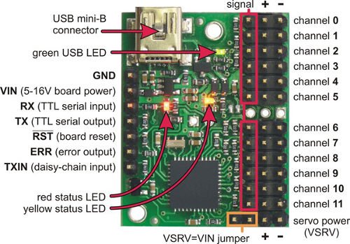
The pinouts are popular goldpin strips (raster 2.54), matching standard servoconnectors and connection wires.
On the board you will find:
- miniUSB connector used to connect the circuit to a PC
- 5V power bus connector for supplying power to other circuits
- connectors to connect the power supply for servos (+ and -)
- connectors for servomechanisms, the pin marked as signal can also be used as analog inputs and digital inputs / outputs working with voltages of 5 V
- status LEDs
- logic power supply connector (useful if the controller will not be permanently connected to the USB port)
- connectors for UART serial communication interface (RX, TX)
Product specification: Mini Maestro USB 12-channel servo controller - Pololu 1352
- Power supply: 5 V to 16 V
- Current consumption: 40 mA*
- Number of channels: 12
- Transmission speed: 300-200000 bps**
- Control methods:
- USB - included PC program
- Serial interface (UART) - e.g. communication with a microcontroller
- scripts stored in the controller's memory
- Dimensions: 28 x 36.5 mm
* When connected to a USB cable, the device consumes 10 mA more
Examples of usage of Maestro
- projects using multiple servos e.g. manipulator
- walking robots e.g. Hexapods
- controlling servos with a computer(USB cable)
- use of channels as general purpose digital outputs
- use of analog input channels e.g. for reading information from sensors (e.g. Sharp 10-80cm) directly on a PC
- in versions 12, 18 and 24 one of the channels can work as PWM output, so you can operate the motor driver (e.g. TB6612FNG)


 Micro
Micro


