Product description: TB6612FNG - 13.5 V / 1 A dual channel motor driver - Pololu 713
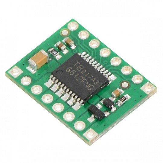
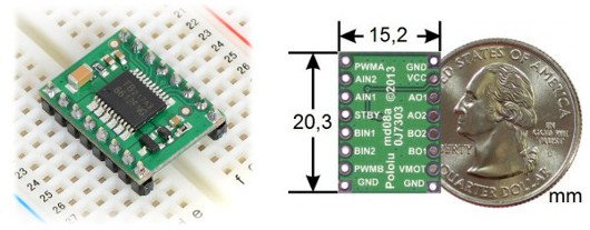
The H-bridge TB6612FNG is an efficient motor driver in a small and SSOP24 housing. Pololu company has met the expectations of users and created a module containing TB6612FNG chip and passive components needed for its proper operation. Signals are provided on traditional pins (2.54 mm pitch). The module can be plugged into contact board or connected with wires.
| For Arduino users, there is a library available, which makes the module easy to use. |
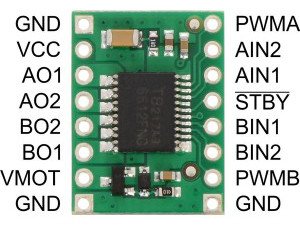
Motor driver pinouts
| Pin | Description |
|---|---|
| VCC | supply of the logic part |
| VMOT | motor supply |
| GND | ground |
| AO1 AO2 | channel A outputs |
| BO1 BO2 | B channel outputs |
| PWMA | PWM signal of channel A |
| PWMB | PWM signal of channel B |
| STBY | should be connected to VCC in order to switch the system on, low state (default) switches the system to sleep mode (low power consumption) |
| AIN1, AIN2 | controlling the direction of the A channel |
| BIN1, BIN2 | controlling the direction of the B channel |
All logic signals are internally pulled to ground. The maximum PWM frequency is 100 kHz.
TB6612 controller truth table
|
AIN1 |
AIN2 |
PWMA PWMB |
Outputs motors |
|---|---|---|---|
|
state |
state low |
% fill (different from zero) |
The motor turns clockwise at the maximum speed set by pwm (different from 0). |
| state low |
state high |
% fill (different from zero) |
The motor turns at the maximum speed set via pwm (different from 0) counterclockwise. |
| state low |
state low |
no meaning |
free braking (soft stop) |
| state high |
state high |
meaningless |
soft stop (soft stop) |
| no meaning |
no meaning |
low state 0% filling |
|
Video of the controller
Video describing operation of H-bridge - DC motor driver.
The TB6612 chip can be used as a controller for Pololu micromotors. If the motors will be exposed to stalling, it is recommended to merge the channels to achieve higher current capacity. To do this, connect the following leads together:
- AO1 with BO1
- A02 with BO2
- PWMA with PWMB
- AIN1 with BIN1
- AIN2 with BIN2
Schematics
The module contains a soldered bridge with goldpin leads, with standard 2.54mm spacing. There are also filtering capacitors on the board, which makes the proper connection with the microcontroller sufficient for proper operation. The schematic is available at this address.
We also offer other motor controllers including separate TB6612 chip.
Pololu TB6612FNG controller specification
- Power supply for motors (VMOT): from 4.5 V to 13.5 V
- Logic power supply (VCC): from 2.7 V to 5.5 V
- Maximum output current: 3 A per channel
- Continuous output current: 1 A per channel
- When both channels are connected: 2 A
- Maximum PWM frequency: 100 kHz
- Built-in thermal cut-off circuit
- Filter capacitors on both supply lines
- Protection against reverse current from motors
Useful links |


