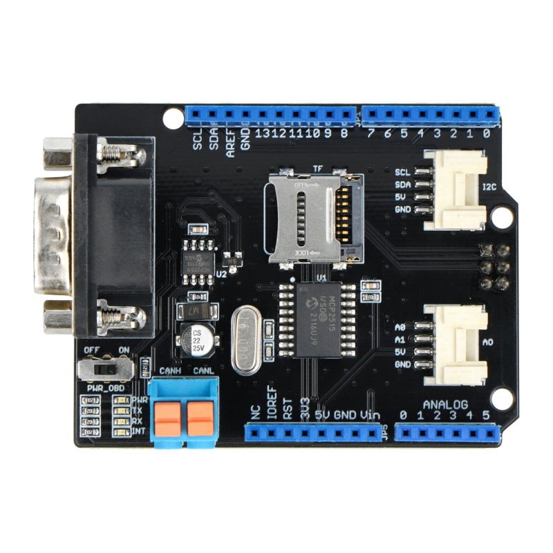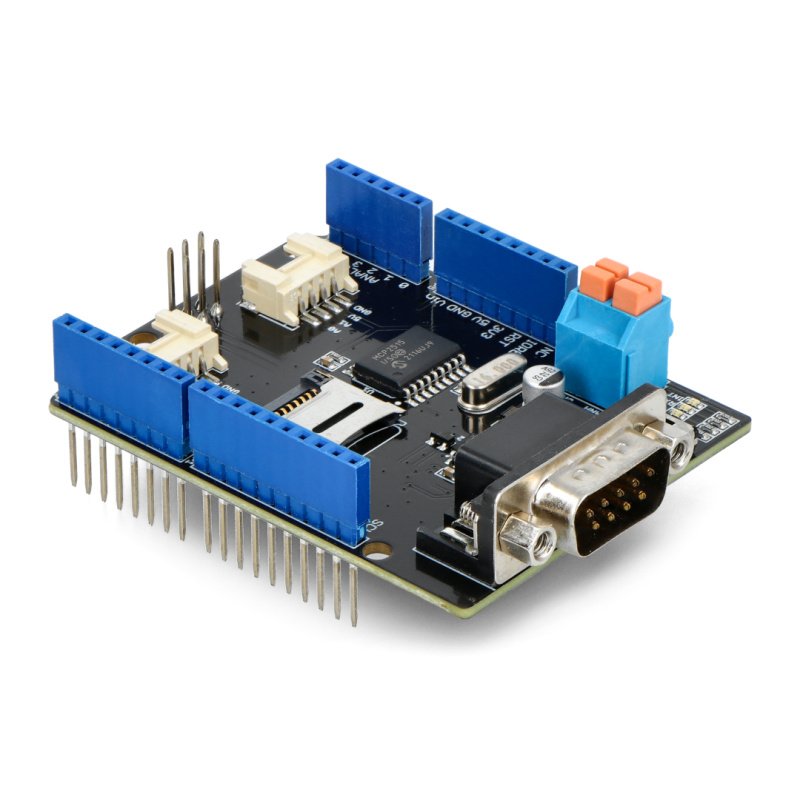


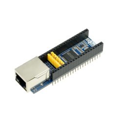

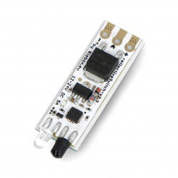

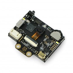
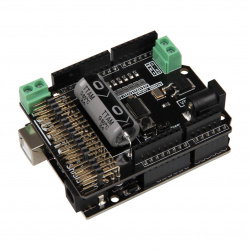


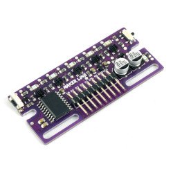


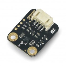


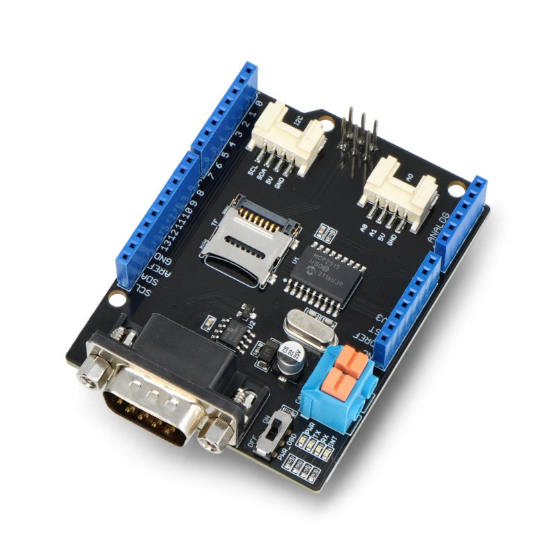


Shield for Arduino supporting the CAN bus. It is equipped with chips MCP2515 and MCP2551. It communicates via the SPI interface. It works with voltage of 5 V.
Shield for the Arduino allows the use of serial busCAN. It is equipped with chips MCP2515 and MCP2551. It communicates via the SPI interface. It works with voltage of 5 V.
A full overview of the module can be found onthe website of the manufacturer.
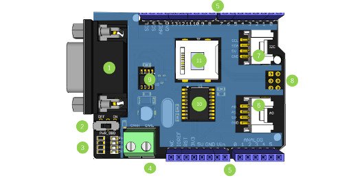
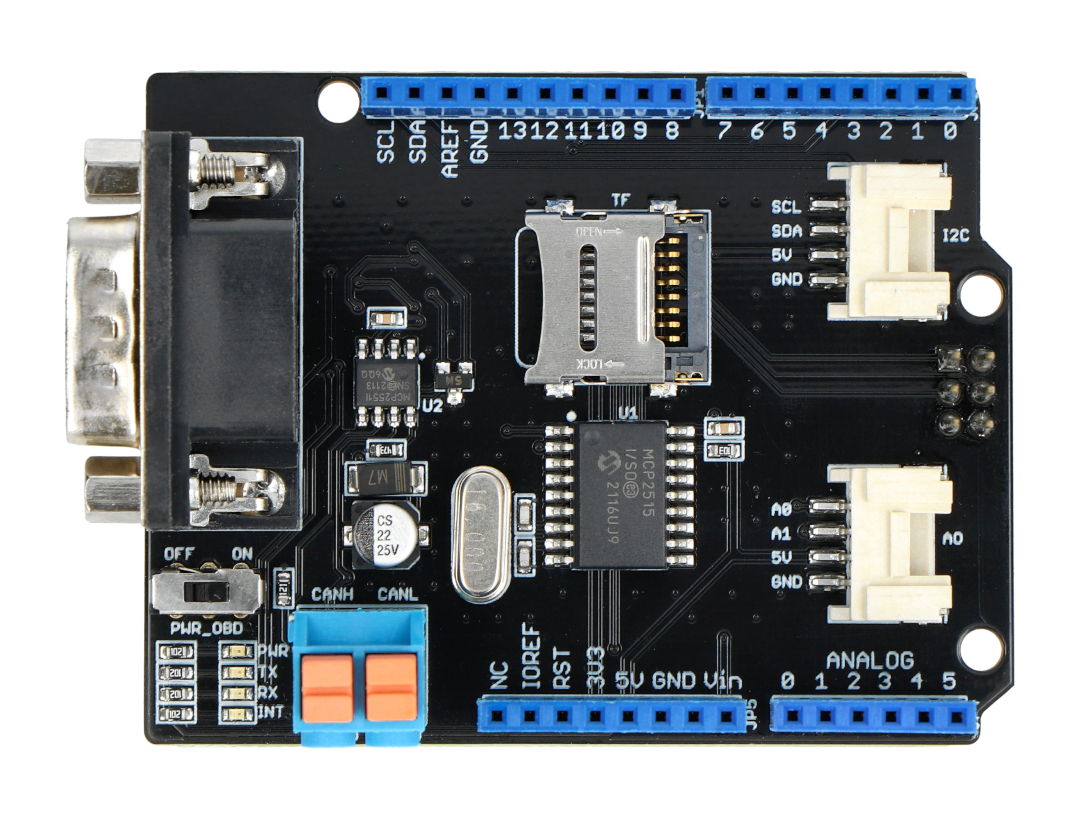
Lines of the CAN bus, i.e. CANH and CANL were led out on the screw connections ARK and on the DB9 connector. The distribution of pins is visible in the figure below.
| Name | Description |
|---|---|
|
1.DB-9 slot |
Connection with OBDII interface via cable DBG - OBD. |
|
2.V_OBD |
Power from the OBDII interface from DB9 slot. |
|
3.LED Indicator |
|
|
4.Connector ARK |
CAN_H and CAN_L. |
|
5.Connectors, pitch of 2.54 mm |
Connectors forArduino. |
|
6.Serial Grove connector |
Connector for communication through a serial port. |
|
7.I2C connector Groove |
Connector for communication through the I2C interface. |
| 8.ISP connector | Connector for connecting via interface ISP. |
|
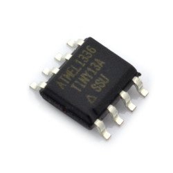
9.ChipMCP2551 |
fast transmitter / receiver CAN. |
|
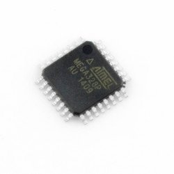
10.ChipMCP2515 |
standalone CAN controller with SPI interface. |
|
11.The SD card slot |
The SD card slot. |
Useful links |
| Niebezpieczne | Component |
| Package width | 7 cm |
| Package height | 3 cm |
| Package depth | 10 cm |
| Package weight | 0.048 kg |
Be the first to ask a question about this product!

Product Information
The product is a component intended for further assembly/prototyping. It does not constitute a standalone finished product within the meaning of product safety regulations.
Dane GPSR
Country of Origin: China
Manufacturer Contact Details: Seeed Technology Co.,Ltd. Tower B 1/F, Shanshui Building, NanshanYungu Innovation Industry Park, Liuxian Ave. No. 1183 CN 518055 Shenzhen [email protected]
EU Marketer Contact Details: BOTLAND B. DERKACZ SP. K. Gola 25A - 63-640 Bralin