Description
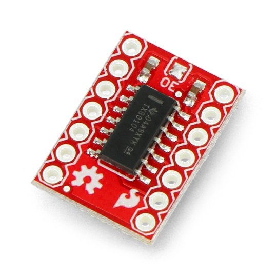
The module is based on a TXB0104 system, it allows you to exchange data between systems that use the most popular voltage levels: from 1.2 V to 3.6 V for VCCA inputs, and from 1.65 V to 5.5 V for VCCB inputs, unless the B part exceeds the voltage of part A. It works in both directions with automatic detection. It has four channels.
The pins are solder fields for soldering the goldpin connectors(2.54 mm pitch). Thanks to them, it is possible to connect the system with thebreadboardor the main module (for example,STM32DiscoveryorArduino) viawires. The size of the converter is 18 x 12 mm. The set does not contain the goldpin connectors, you can purchase them separately.
|
The manufacturer provides the design files on GitHubandthe instruction describing the connection method of the converter. |
Example of usage
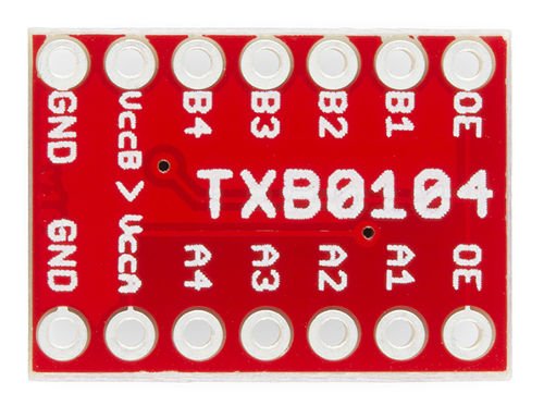
Converter is easy to use, for correct operation, it is sufficient to connect the power supply of two systems that will be converted. A higher voltage (e.g. 5 V) must be connected to the B pins (high voltage), lower (e.g., 3.3 V, 2.8 V and 1.8 V) to A pins(low voltage). Grounds are connected to the pins marked with GND symbol. Logic signals should be led to the corresponding connectors B1, B2, B3, B4 - higher voltage and respectively A1, A2, A3, A4 - lower voltages.
Useful links |


