Product description: Feather RP2040 - board with RP2040 microcontroller and USB A host - Adafruit 5723
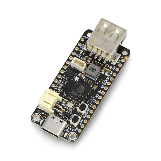
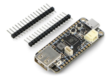
A board from Adafruit - Feather RP2040 with a USB type A host. It is based on the RP2040 microcontroller from the Raspberry Pi Foundation , with a dual-core ARM Cortex M0+ clocked at up to 133 MHz , with 264 kB of RAM and 8 MB of Flash memory operating via the QSPI interface. The module pins include as many as 21x GPIO pins - 4x ADC 12-bit, 2x I2C, 2x SPI, 2x UART, 16x PWM. The Feather RP2040 board can be programmed using MicroPython, CircuitPython or C/C++. The program can be implemented via the USB interface (USB Type C connector), using the built-in UF2 bootloader, or via an external programmer .
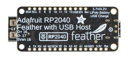
The board is equipped with the RP2040 system.
Also check the user guide prepared by the manufacturer.
Main features of the Adafruit tile
- 32-bit dual-core Cortex M0+ operating at a frequency of up to 133 MHz with a logic voltage and 3.3 V power supply
- As much as 264 kB of built-in SRAM memory
- 8MB SPI Flash memory for storing CircuitPython/MicroPython files and code (no EEPROM)
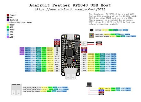
- 21x GPIO, including: 4x ADC 12-bit, 2x I2C, 2x SPI, 2x UART, 16x PWM
- 200 mA+ lithium polymer charger system with assigned LED indicating charge status
- RGB NeoPixel diodes and red LED (pin 13)
- STEMMA QT connector for quick and solder-free connection of any peripheral devices with a Qwiic, STEMMA QT or Grove I2C connector
- USB Type-C connector allowing access to the onboard USB ROM bootloader and serial port debugging
- USB type A connector enabling USB host support (D+ pin GPIO 16, D- pin GPIO 17)
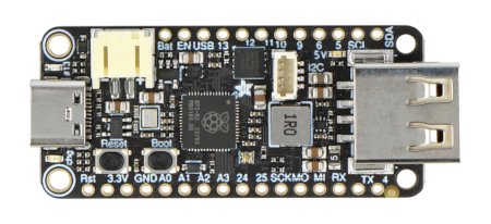
Pinouts of the Feather RP2040 board
- USB Type C connector - used for power supply and data transfer, allows code and software updates
- USB type A connector - used to connect an additional USB device, currently this USB host function is only available in Arduino
- JST connector - a 2-pin connector for connecting a Li-Ion or Li-Pol battery that will power the board, it can also be used to charge the battery
- chg LED - LED indicating the charging status of the connected battery when charging via the USB port
- GND - system ground
- BAT - positive voltage common to the JST socket for the optional battery
- USB - positive voltage common to the USB C socket
- EN - pin enabling the built-in 3.3 V regulator, to turn it off, connect it to ground
- 3.3 V - voltage stabilizer pins
More information about the remaining pins of the board can be found here .
Technical specifications of the board
- Built-in chip: Raspberry Pi RP2040
- Core: ARM Cortex-M0+ Dual-Core 133 MHz
- SRAM memory: 264 kB
- Built-in QSPI Flash memory: 8 MB
- Communication interfaces: 2x SPI, 2x I2C, 2x UART, 4x 12-bit ADC, 16x PWM
- Development environment: C/C++ or MicroPython
- Power connector: USB Type-C
- Pinouts: GPIO, STEMMA QT / Qwiic, USB type A connector
- Power connector: JST connector for connecting the battery
- Stabilizer: 3.3V with 500mA peak current output
- Voltage converter: 5V Boost
- Mounting holes: 4x
- Dimensions: 51 x 23 x 7 mm
Useful links |
