- Discontinued product
- SPECIAL OFFERS
Description
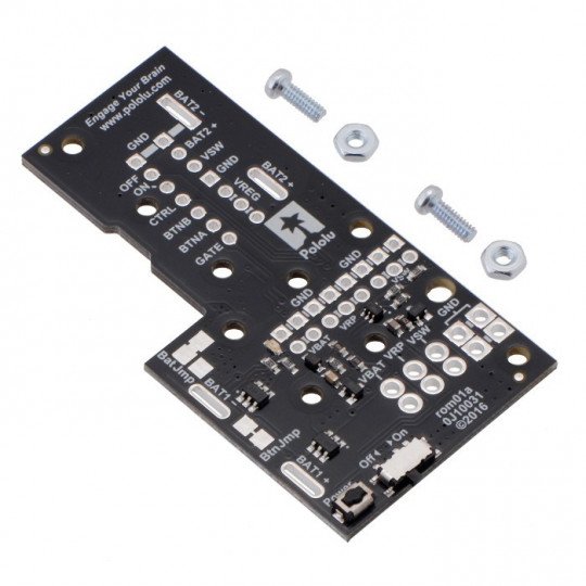
The power module is designed for Romi Chassis. It facilitates the use of energy of the battery for the rest of the elements. It has a power switch, a few power supply options, and reverse polarity protection. The board has a button and the ability to mount the additional buttons or other powercontrol features.
Connection
The default built-in button controls the power. One switch turns on the module, and the second, turns it off. To the board, you can attach the extra buttons. However, the buttons with excessive shaking of the contacts (few ms) may not work properly.
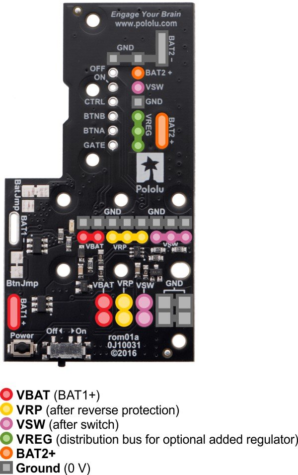
Pins on the module are as follows:
| PIN | Description |
|---|---|
| BTNA | Connection via the temporary button with BTNB, it provides the ability to turn on and off. The ground connection provides only the possibility of turn on. |
| BTNB | Connection via the temporarybutton with BTNA, provides the ability to turn on and off. |
| ON | High status (over 1V) switches the system on. It works only when the button's functions are turned on (so-called jumper's buttons are connected). |
| OFF | High status (over 1V) turns the system off (e.g. allows for the powered device to turn off its own power). It works only when the button's functions are turned on (so-called jumper of the buttons is joined). |
| CTRL | When the buttons' functions are enabled, it determines the status of the system. High status (over 1V), turns it on, and low, turns it off. Not connected, does not determine the status.CTRL and OFF pins can't be in a high status at the same time. |
| GATE | When the buttons' functions are disabled, this pin controls the status of the system. A low status turns it on, and unspecified status, turns it off. Connected via slide switch or lever switch to the ground to turn on and off. Disconnected, it enables for the operation of the buttons. It is recommended to leave the pin unconnected or connected to the ground.You mustn't set a high status when the slide switch is in the OFF position. |
| VBAT | Connected to BAT1+, it provides the direct battery voltage. By default, it is connected with all 6 batteries (see below). |
| VRP | Connection with the batteries through protection from reverse polarity. |
| VSW | Connection with the batteries through protection from reverse polarityand a switch. |
| VREG | Unconnected, along with VSW, it allows for the connection of an external voltage regulator. For example, the connection of the D24V5F5 converter, provides a stable 5 V to power the microcontroller, e.g.an Arduino. |
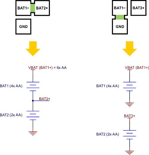
| BAT2+ | Allows for the power from two batteries. It is useful when there are two power sources (see below). |
Power setting
By default, the module provides power from all 6 batteries (voltage of 7.2 V with the rechargeable batteries or 9 V with the alkaline batteries). Jumper marked with the Bat Jmp,allows you to split the power into two independent sections:Bat1 from 4 batteries (4.8 V voltage with the rechargeable batteries or 6 V with alkaline batteries) andBat2 from 2 batteries (voltage of 2.4 V onrechargeable batteries or 3 V with the alkaline batteries). Disconnecting the Bat1-andBat2+, and then connecting the Bat1-with the GND,we get a total groiund for the two power sources.
| Connection of the Bat1- with the GND before the disconnection of the Bat1- and Bat2+ results in the short-circuit in the Bat2 section. |
Useful links |
