


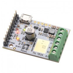


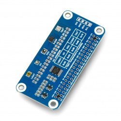


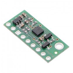


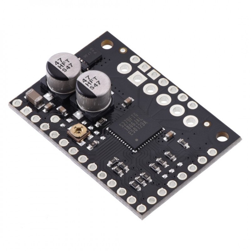


Stepper motordriver based onTB67S279FTGchip . Powered by a voltage range of 10 - 47 V, with a maximum current consumption of 2 A per coil. Maximum resolution: 1 / 32 steps. Thanks to the TB67S279FTG driver, the chip can dissipate more heat, which allows 1,2 A current flow without a heatsink.
The circuit allows tocontrol a stepper motorwith a device that allows togenerate logic states, e.g.Arduino,STM32Discovoery,Raspberry Pior anymicrocontroller.Pololu module is characterized by verysimple operation. Rising edge of each impulse on CLK (STEP) pin corresponds to one step.Selection of the direction is performed by giving the appropriate state to the CW/CCW (DIR) pin (e.g. low state - clockwise rotation, high state - anticlockwise rotation). The controller can also selecttheresolution ofmotor operation.
To control a bipolar stepper motor you should connect the system according to the diagram below.
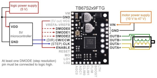
Minimum wiring diagram to connect the microcontroller to the TB67S2x9FTG.
The controller requires a supply voltage from 10 V to 47 V, which will be connected to the VIN and GND pins.
To supply the logic part of the module requires a voltage of 5 V, which should be connected to pinVDD PIN. The motor supply voltage from 10 V to 47 V is applied to the pinVIN PIN.
|
Caution! Connecting and disconnecting the motor while the controller is on can damage the system. |
The step size is selected using the DMODE0, DMODE1, DMODE2 inputs. The possible settings are shown in the table below. The MS1, MS2 and MS3 inputs have an internal pull-down resistor (100kΩ).
| MS1 | MS2 | MS3 | Resolution |
| low | low | low | Standby mode |
| low | low | high | Full step |
| low | high | low | Non-wheeling half step ('a') |
| low | high | high | 1/4 step |
| high | low | low | circular half step ("b") |
| high | low | high | 1/8 step |
| high | high | low | 1/16 step |
| high | high | high | 1/32nd step |
The rising edge of each pulse on the CLK pin (STEP) corresponds to one step. The direction is selected by applying the appropriate state to the CW/CCW (DIR) pin (e.g. low state - clockwise rotation, high state - counterclockwise rotation). If the motor is to rotate in one direction only, the DIR pin can be left unplugged.
When the RESET pin goes high, the driver resets its state in the translator array, which outputs to the initial value of 45°. This corresponds to 100% of the current limit on both coils in full step and non-wheel half step modes. The RESET pin does not disable the motor outputs, the controller will continue to supply current to the motor but will not give information to the CLK output
The TB67S2x9FTG can detect several error conditions that report causing one or both LO pins to be low. The manufacturer has includeda table of error combinations on the LO1 and LO2 pinsin thedocumentation.
A detailed description of each pin can be found on themanufacturer's website.
Useful links |
| Package width | 8.5 cm |
| Package height | 0.8 cm |
| Package depth | 7 cm |
| Package weight | 0.01 kg |
Be the first to ask a question about this product!
Country of Origin: United States
Manufacturer Contact Details: Pololu Corporation 920 Pilot Rd. Las Vegas, NV 89119 USA [email protected]
EU Marketer Contact Details: BOTLAND B. DERKACZ SP. K. Gola 25A - 63-640 Bralin


