Products for which the sale has been cancelled.
- Page
- View all
- 3D print
- Minicomputers
- Electronics
- Sensors
- Robots & mechanics
- Tools & Power Supplies
- Education
- Smart Home
- Others
- 3D PRINTING
- View all
- 3D printers
- Filaments
- Accessories for 3D printers
- Replacement parts for 3D printers
- Creative kits for 3D projects
- Filament dryers
- Postprocessing and filament merging systems
- Resins for 3D printers
- Components for 3D printers construction
- 3D scanners
- 3D Pens
- CNC
- MINICOMPUTERS
- View all
- Raspberry Pi
- Arduino
- Nvidia
- Flipper Zero
- XIAO
- Odroid
- BBC micro:bit
- Other minicomputers
- M5Stack
- ESP32
- PLC drivers
- ELECTRONICS
- View all
- Computer accessories
- Automobile accessories
- Cooling
- Diodes
- Sound and acoustics
- Mounting components
- Passive elements
- Wearables (e-textiles, smart clothes)
- Cameras
- Consoles
- Memory cards & disks
- Communication
- Converters
- Electronics courses
- Microcontrollers
- Animal repellers
- LED lighting
- Programmers
- Relays
- Voltage regulators
- Artificial intelligence
- Motor drivers and servos
- Integrated circuits
- Displays and screens
- More...
- SENSORS
- View all
- Alarm sensors
- Inductive sensors
- Piezoelectric sensors
- 9DoF IMU sensors
- Oxygen sensors
- Pressure sensors
- Twilight sensors
- Door sensors
- Gas sensors
- Optical sensors
- Tilt sensors
- Accelerometers
- Air quality sensors
- Sound sensors
- Gesture sensors
- Inductive contactless sensors
- Grove modules
- Gravity modules
- Limit switches
- Sensors of light and color
- Magnetic sensors
- Medical sensors
- Pressure sensors
- Sensors odbiciowe
- Distance sensors
- Weather sensors
- Liquid level sensors
- Current sensors
- Flow sensors
- Motion sensors
- Temperature sensors
- PT100 temperature probes
- Humidity sensors
- Fingerprint readers
- Encoders
- Hall effect sensors
- Photoresistors
- RPM sensors
- Phototransistors
- IR receivers
- Magnetometers
- Resistance sensors
- Gyros
- Sensor sets
- More...
- TOOLS AND POWER SUPPLIES
- View all
- Tools
- Soldering
- Power supply
- Oscilloscopes
- Measuring instruments & devices
New products
- New
Promotion products
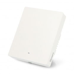
Sonoff M5-1C-80W - WiFi/Matter smart wall switch - 1 channel - white
Index: INN-25502
- Reduced price
- Sale
- Reduced price
- Sale
- Reduced price
- Sale
Withdrawn products
Loading...
Power supply 12V/1,5A - plug DC 5,5/2,1mm
Stabilized mains power supply. Supply voltage: 100 V - 240 V. Output voltage: 12 V DC. Output current: 1.5 A. Has a 5.5 x 2.1 mm DC plug.4.9 (17)
Index: SPT-13758
Index: SPT-13758
Shipping in 24 hours
Available
- Sale
See also


