Description
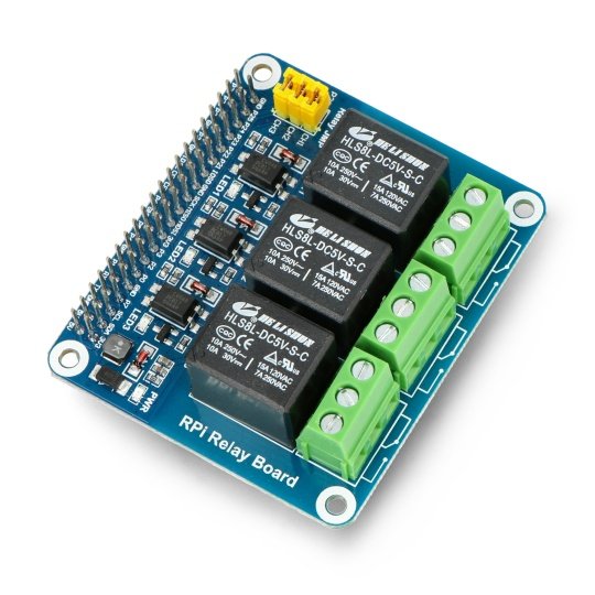
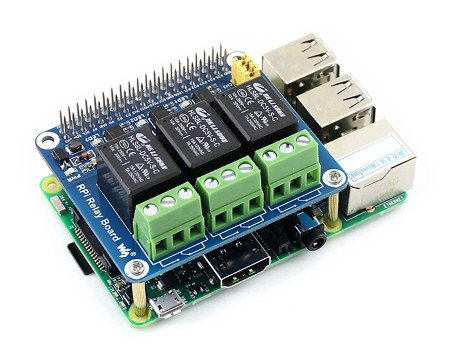
Cap fitted to connectors of Raspberry Pi GPIO in version 4B, 3B+, 3B, 2B, B+ and A+, with three relays with parameters of 250 V / 10 A. Board has a screw connector. Communication via digital signals.
Cap has connectors suitable forthe Raspberry Pi, three relays and screw connectors. Minicomputer can be purchased separately.
Specification
- Power: consumed from a Raspberry Pi
- 3 x relay with the following parameters:
- 250 V AC / 10 A
- 120 V AC / 15 A
- 30 VDC / 10 A
- Connectors are compatible with the Raspberry Pi
- Optical isolation separating the system and control
- Status LEDs
- Four holes for the mounting screws
- Mounting elements included
- Dimensions: 65 x 56 mm
Connection
The module communicates via the digital signals via the GPIO pins of the Raspberry Pi. Below is the schedule of used leads along with the markings of GPIO for library wringPi and in nomenclature of the BCM processor.
| Relay |
Pin GPIO |
Library wiringPi |
Marking of the system BCM |
|---|---|---|---|
| Channel 1 | 37 | P25 | 26 |
| Channel 2 | 38 | P28 | 20 |
| Channel 3 | 40 | P29 | 21 |
|
A detailed description and an example of configuration from minicomputer, can be found inthe user guide. |
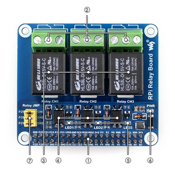
The distribution of elements on the board
- GPIO connectorto connect to the Raspberry Pi
- The screw connectors to connect the managed device
- Relays
- Opto-isolators PC817
- LEDs:
- On: NC is open and NO closed
- Off: NC - closed and NO open
- Closed: control of relays by default inputs and outputs from the sample code
- Open:control of relays input by inputs and outputs via wires
Useful links |


