Product description: DRV8434 stepper motor driver 48 V / 2 A - with pin connectors - Pololu 3763
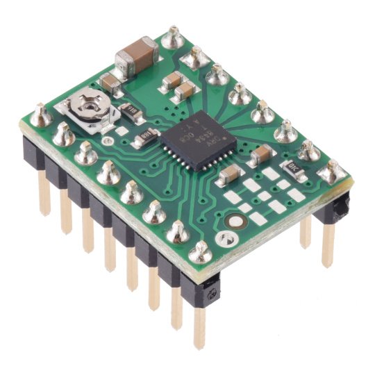
Stepper motor driver module based on the Texas Instruments DRV8434 chip with male pins installed for connection to a 16-pin socket or breadboard without the need for soldering . It allows you to control a stepper motor with a maximum current consumption of up to 2 A per coil and supports a supply voltage from 4.5 V to 48 V. It offers a wide selection of step resolutions, from full step to 1/256 step . It supports six current decay modes, including two intelligent adjustment modes that ensure smooth steps without the need for manual tuning. Current regulation using a built-in potentiometer allows the use of higher than rated voltages, which allows for higher step speeds. Thanks to the integrated voltage regulator, no additional power supply is required for the logic part. The module has the same size and pinout as the A4988 controller, which allows it to be directly replaced in many applications.
Our offer also includes drivers for stepper motors with other operating parameters.
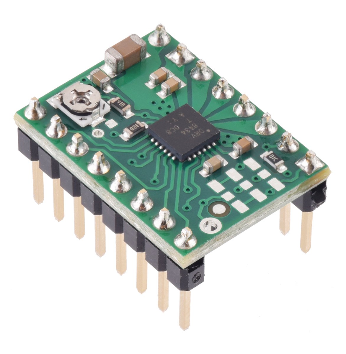
DRV8434 stepper motor driver 48 V / 2 A - with pin connectors - Pololu 3763.
Main features of the controller
- Pre-installed pin connectors - no soldering is required to use the module with a suitable 16-pin socket or breadboard.
- Supply voltage range: 4.5V to 48V.
- Maximum current per coil: 2 A, up to 1.2 A without additional cooling.
- Step resolution: from full step to 1/256 step.
- Ability to work in eleven modes: full step with 100% current, full step with 70% current, partial 1/2-, 1/2-, 1/4-, 1/8-, 1/ 16-, 1/32- , 1/64-, 1/128-, 1/256-step
- Current regulation: built-in potentiometer allows easy adjustment.
- Integrated voltage regulator: no additional power supply needed for the logic part.
- Current decay modes: Advanced modes, including Smart Tune, optimize motor performance.
- A4988 compatible: size and pinouts compatible with the popular A4988 driver, allowing for easy replacement.
- Protections: protection against overload, overheating and undervoltage.
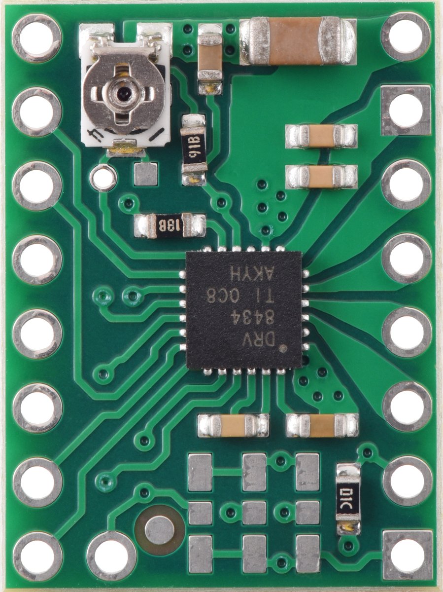
- Exposed ground field from the bottom: allows soldering of cooling elements
Connecting the module
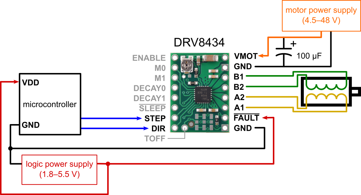
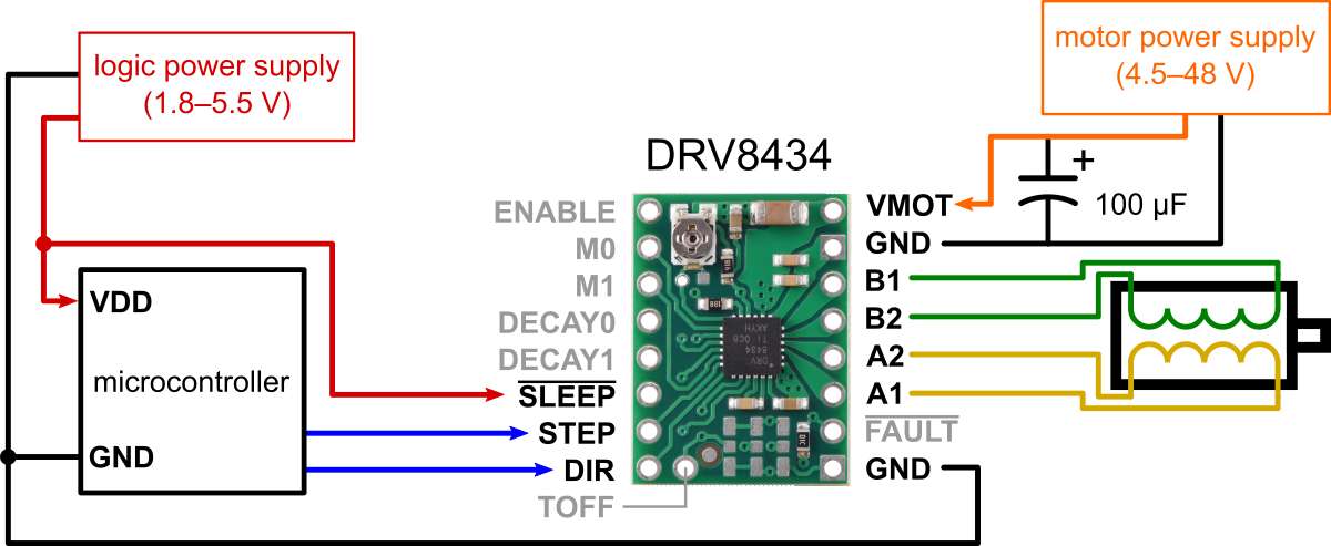
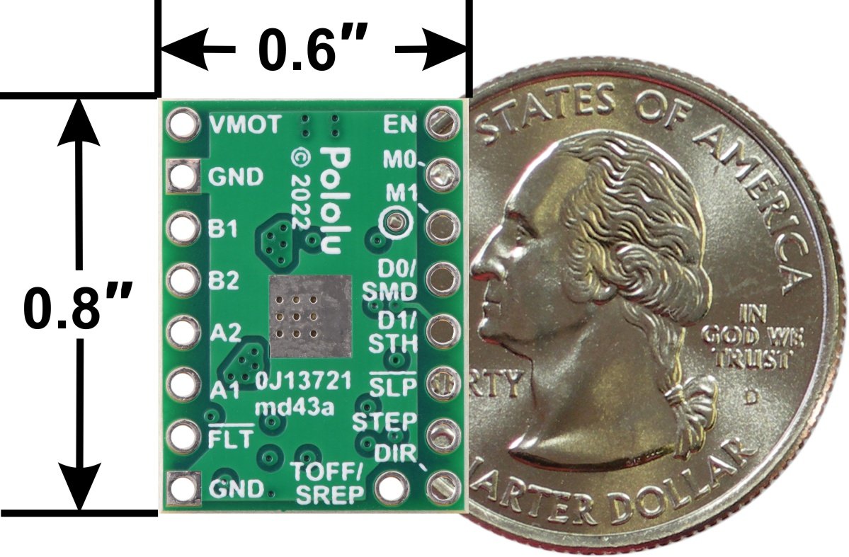
The controller requires a motor supply voltage from 4.5 V to 48 V, which should be connected via VIN and GND. Please note that supply voltages below 6V limit the maximum current limit that can be set.
Controller control
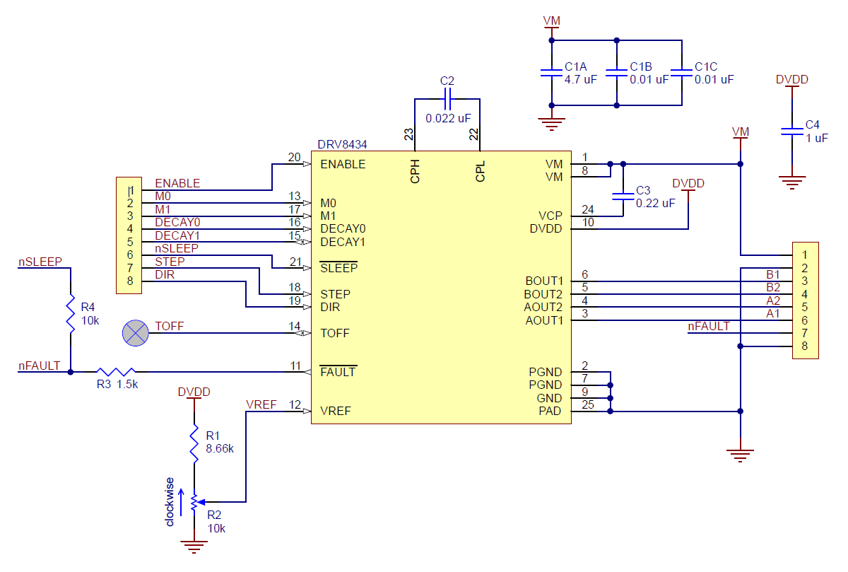
- STEP and DIR inputs: the rising edge of each pulse on the STEP pin corresponds to one microstep of the stepper motor in the direction set by the DIR pin. Both of these pins are attracted to ground (GND) by default. If the motor rotates in one direction, the DIR pin may remain unconnected.
- DECA0 and DECA1 inputs: allow you to select one of six current decay modes, depending on the direction of increasing or decreasing steps.
- SLEEP and ENABLE inputs: the SLEEP (SLP) pin is internally pulled low, which by default disables controller operation. To activate it, a high state must be supplied to this pin. The ENABLE pin is used to select the overload and overheat protection operation mode.
- FAULT output (FLT): When faults are detected, such as undervoltage, overload, open load, stop detection or overheating, the FAULT output goes low. On the board it is connected to the SLEEP pin, which pulls the FLT up to the supply voltage (VCC), making it compatible with the A4988 version.
Step size
The step size is selected using the M0 and M1 inputs. The method of obtaining the appropriate step resolution is presented in the table below.
| MODE0 | MODE1 | RESOLUTION |
| Low | Low | Full step with 100% current |
| High | 330 kΩ to GND | Full step with current 70% |
| High | Low | Less than 1/2 step |
| Hi-Z | Low | 1/2 step |
| Low | High | 1/4 step |
| High | High | 1/8 step |
| Hi-Z | High | 1/16 step |
| Low | Hi-Z | 1/32 of a step |
| Hi-Z | 330 kΩ to GND | 1/64 step |
| Hi-Z | Hi-Z | 1/128 step |
| High | Hi-Z | 1/256 step |
Current limit
Current limiting is crucial to achieving high stepping speeds, especially when the motor power supply exceeds the nominal values. For example, a standard stepper motor might have a maximum current rating of 1 A with a coil resistance of 5 Ω, which would mean the maximum power supply to the motor is 5 V. Using a higher voltage, such as 9 V, allows for higher step speeds, but is necessary there is an active current limitation below 1 A to avoid motor damage.
The controller enables active current limitation by adjusting with a potentiometer. One way is to set the controller to full step mode and measure the current flowing through one coil without supplying a signal to the STEP input.
Alternatively, you can measure the voltage at the VREF pin and calculate the current limit. The current limit can be calculated using the following formula:
Current limit = VREF / 1.32
Technical Specifications
- Supply voltage: 4.5V to 48V
- Continuous current per coil: 1.2 A
- Maximum instantaneous current per coil: 2 A
- Logic part supply voltage: from 1.8 V to 5.5 V
- Number of operating modes: 11
- The module has soldered pins
- Dimensions: 20 x 15 mm
- Weight: 1.3 g
