


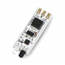
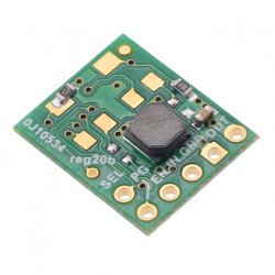


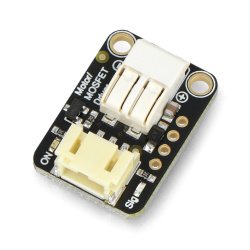
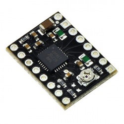


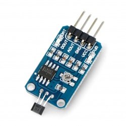

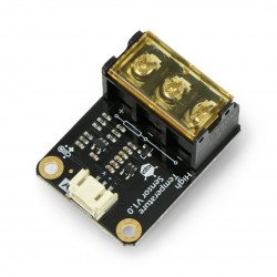


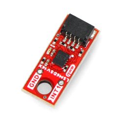


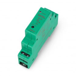


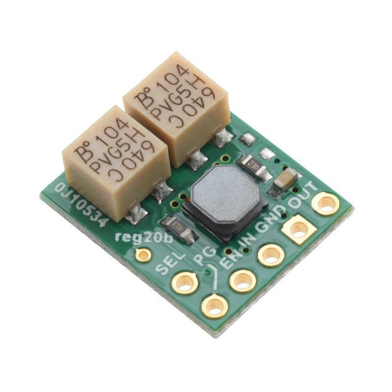


Miniature boost converter module supplied with voltage from 3 V to 16 V. Output voltage adjustable from 2,5 V to 9 V. Maximum current 1,5 A. Dimensions: 15 dimensions: 15 x 13 x 6 mm. The voltage cut-off function with hysteresis is used to prevent the battery from discharging too much.
The converteris used to supply circuits with voltage from 2.5V to 9V. The circuit has a wide range of input voltages, which makes it ideal for battery powered designs. Application of S9V11MACMA ensuresstability of power supplyduring the entire cycle of battery discharge. In order to increase reliability, the module is equipped with short-circuit protection and automatic power cut-off system when the permissible operating temperature or minimum voltage is exceeded.
|
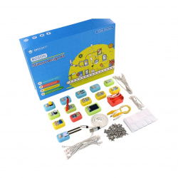
We also offer a set to build asmartphone charger with on-line manual. |
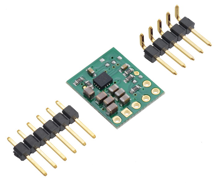
The set includes goldpins for individual soldering.
The module is very simple to use, it has three basic leads:
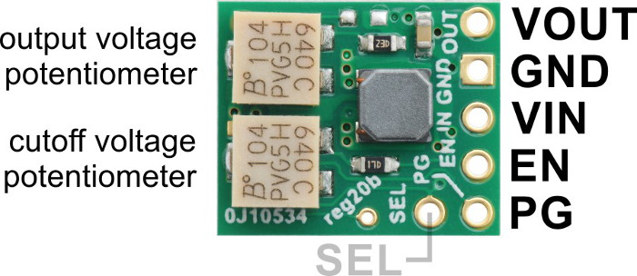
Additional pins:
The acceptable input voltage range is from 3 V to 16 V. The regulator will not turn on at a lower value. A higher voltage may damage the circuit.
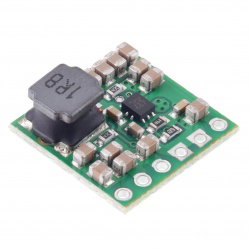
The connectors are properly signed on the board.The pinout is 2.54 mm (goldpin connectors). The module can be plugged into thecontactboard, connected bywiresor soldered into a dedicated PCB.
Output voltage is regulated by a built-in potentiometer. Turning clockwise increases the output voltage, which should be measured with a meter.
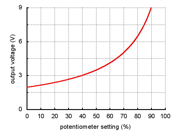
The voltage can be set below 2.5 V and above 9 V, but the device may then operate unstably. We recommend using the range specified by the manufacturer. Voltage may be 3% higher with little or no load. It may also drop depending on the current draw, especially when the input voltage is lower than the output voltage. However, it should be within 5% of the error.
A VIN voltage that is too low to cause a power cutoff is controlled by the potentiometer and the EN pin. When the voltage on EN drops below 0.7 V, the chip sets itself to a low power state - sleep mode. When 0.8 V is received at the EN pin, the chip returns to operation. Turning the potentiometer clockwise increases the cutoff voltage. This voltage can be set by measuring VIN and EN and adjusting the potentiometer according to a formula:
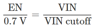
For example, if a 3.7 volt battery is connected to VIN and the cutoff voltage is to be 3.0 volts, the formula will be as follows:
EN is equal to 0.86 V, so spin the potentiometer until this is the voltage you can measure on the EN pin.
Note that the cutoff level includes hysteresis. The regulator will shut down at 0.7 V, but you must apply about 0.8 V to get it to start up again. The VIN voltage must be equal to approximately 114% of the cutoff voltage to restart (3.43 V in the above case).
The maximum current that can flow through the circuit depends on the value of the input voltage. This relationship is shown in the graph below:
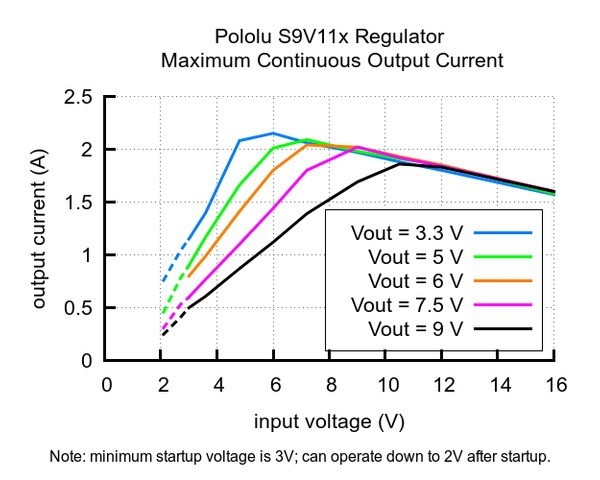
Maximum output current as a function of input voltage.
This parameter is especially important with battery power supply, when it is important for the system to work as long as possible on a single charge. The efficiency of the converter depends on the current flowing and the input voltage (graph below). On average, it is between 85% and 95%, which makes it possible to use practically the maximum energy from the battery.
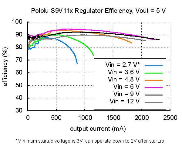
The efficiency of the converter depending on the current consumed.
In electronic circuits, the starting current may cause so-called spikes, sudden voltage jumps to a value above a set level. If the amplitude of the spikes exceeds the allowable value of the regulator, the regulator can be destroyed. Therefore, if the circuit will be supplied with voltage above 9 V or the load will have high inductance, we recommend soldering a capacitor of 33 µF / 20 V or higher as close as possible to the circuit between VIN and GND.
Useful links |
| Length | 15 mm |
| Width | 12 mm |
| Height | 3 mm |
| Voltage to | 2.0 V |
| Voltage from | 16.0 V |
| Voltage output from | 2.5 V |
| Output voltage to | 9.5 V |
| Current | 1.5 A |
| Stabilizer - Type2 | switching |
| Stabilizer - Type | step-up/down |
| Niebezpieczne | Component |
| Package width | 7.5 cm |
| Package height | 0.6 cm |
| Package depth | 8.5 cm |
| Package weight | 0.003 kg |
Be the first to ask a question about this product!
Product Information
The product is a component intended for further assembly/prototyping. It does not constitute a standalone finished product within the meaning of product safety regulations.
Dane GPSR
Country of Origin: United States
Manufacturer Contact Details: Pololu Corporation 920 Pilot Rd. Las Vegas, NV 89119 USA [email protected]
EU Marketer Contact Details: BOTLAND B. DERKACZ SP. K. Gola 25A - 63-640 Bralin


