Description
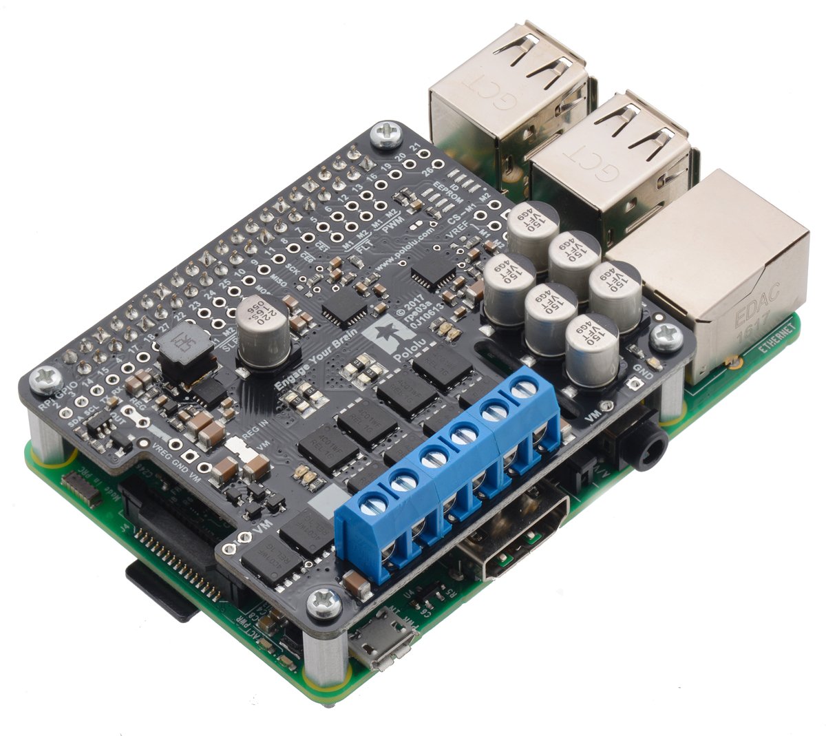
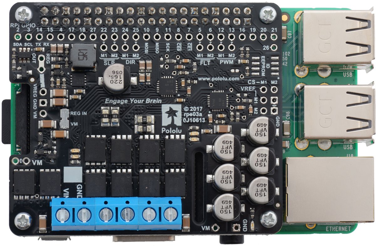
Shield with dual-channel driver pf motors operating with voltages from 6.5 V up to 30 V and current up to 18 A per channel (max 50 A). The system can be connected directly with GPIO connectors of minicomputer Raspberry Pi GPIO 3, 2, B+ and A+. The rotation speed can be controlled by the control signalPWM.
|
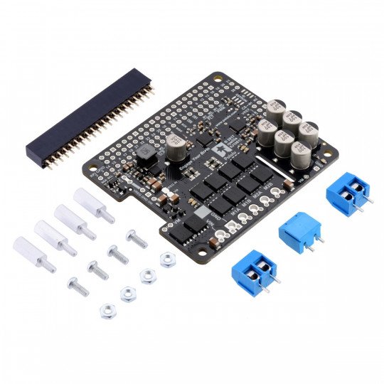
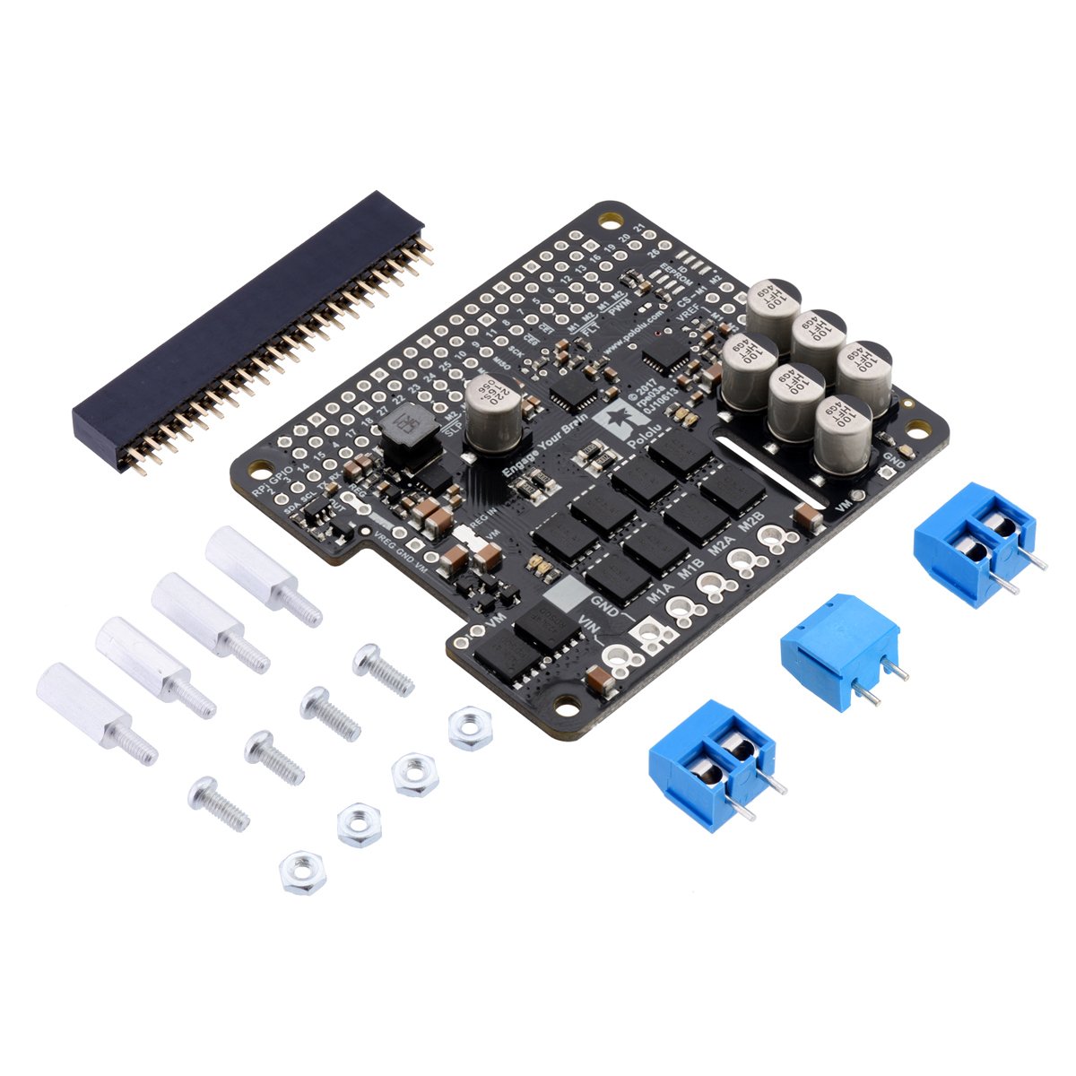
The kit includes: module, screw connection, goldpin strip, screws and spacers for the self-installation. |
In combination with the Raspberry Pi, when using a specially prepared library you can easily control the speed and direction of rotation of two DC motors. Form and pins of the board to allow direct connection to minicomputer. The system uses a 40-pin GPIO connector.
The subject of sale is the shield with the driver of motors, minicomputer Raspberry Pi can be purchased separately.
|
The product is compatible with Raspberry Pi The manufacturer provides a library of Python for users of the Raspberry Pi. |
Modes of operation
The power supply of the motors was separated from the Raspberry Pi. Voltage from a range of 6.5 V to 30 V should be connected to pins VIN and GND. Power supply of the logic part 3.3 V is consumed from minicomputer.
Connection
The following table shows which pins of the Raspberry Pi are used by driver of motors:
|
Pin RPi GPIO |
Pin of driver |
Description |
|---|---|---|
| 5 | Motor 1 FLT |
Status pin. By default, in the high state. When an error of driver is detected, the driver switches to a low state. |
| 6 | Motor 2 FLT |
Status pin. By default, in the high state. When an error of driver is detected, the driver switches to a low state. |
| 12 | Motor 1 PWM |
The PWM inputs to control the rotation speed of the motor. The maximum PWM frequency is 100 kHz. |
| 13 | Motor 2 PWM |
The PWM inputs to control the rotation speed of the motor. The maximum PWM frequency is 100 kHz. |
| 22 | Motor 1 SLP |
By default, in the low state, it indicates the disabled outputs of the motors. To run the driver, you must specify the high status. |
| 23 | Motor 2 SLP | By default, in the low state, it indicates the disabled outputs of the motors. To run the driver, you must specify the high status. |
| 24 | Motor 1 DIR |
Pin to choose the direction of rotation. In the low state, the current flows from output A to B. In high state - from B to A. |
| 25 | Motor 2 DIR | Pin to choose the direction of rotation. In the low state, the current flows from output A to B. In high state - from B to A. |
Modes of operation
The table shows the operation modes depending on the inputs:
| SLP | DIR | PWM | MxA | MxB | Mode |
|---|---|---|---|---|---|
| 1 | 0 | PWM | PWM (H/L) | L | Forward rotation at a certain speed PWM %. |
| 1 | 1 | PWM | L | PWM (H/L) | Back rotation at a certain speed PWM %. |
| 1 | x | 0 | L |
L |
Braking (outputs connected to ground). |
| 0 | x | x | Z | Z | Disabled output. |
Key features
- The LEDs indicate the operation when the motor is not connected
- Built-in regulator step-down switching voltages 5 V / 2.5 A Raspberry Pi for the same power
- A Python library to help you get started with the mototr's control unit
- Protection against reverse power connection
- The short-circuit protection
- Undervoltage shutdown
- Working voltage: 6,5 V to 36 V
- Output current:
- continous: 18
- short-term: 50 And
- Number of channels: 2
- The maximum PWM resolution: 100 kHz
- A kit for self-assembly
- Dimensions: 65 x 56 mm
- Weight: 20 g
|
The driver does not have auto off function when exceeding the permissible temperature. |
Useful links |


