Specification
- Motor supply voltage: 6 V - 30 V
- Current: 1 max., 8 A on the coil (ifapplying coolingto 3 A)
- Voltage digital logic supply: 2.5 V to 5.5 V
- Inputs operate at the voltage from 3.3 V to 5 V
- Standard interface control
- Ability to change parameters via the SPI bus
- Limiting the maximum current through the SPI bus from 132 mA to 3000 mA
- Work in 5 different modes: full-step, 1/2, 1/4, 1/8 1/16, 1/32, 1/64, 1/128 step
- Protection against reverse power connection
- Temperature protection
- Dimensions: 25.4 x 30.5 mm
- Weight: 4 g
Set includes
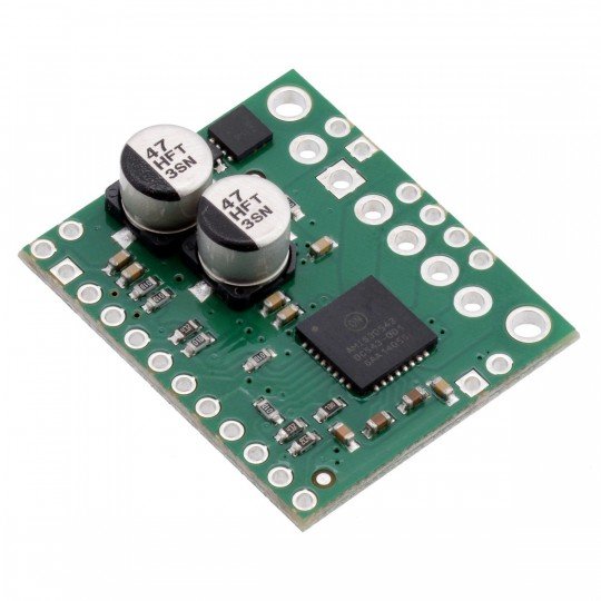
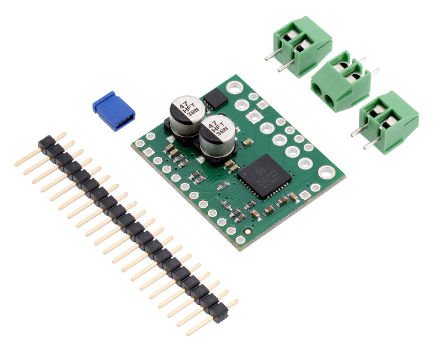
- Module stepper motor driver
- Goldpin strip
- Screw
Description
The system allows you to control a stepper motor using a device that allows you to generate the logical state, for example,Arduino,STM32Discovoery,Raspberry Pior anymicrocontroller. ModuleAMIS-30543is characterized by a very simple operation.
In order to rotate the motor one step, you must specify the output NXT (STEP) high (logical unit), another sequence of zeros and ones moves the motor one step, etc. Choice of direction is accomplished by depositing on the output DIR (e.g. high - turn in a clockwise direction, low - counterclockwise). The driver also has the choice of theresolutionof the motor and to limit the maximum current. These settings are made through the SPI bus.
Inputs
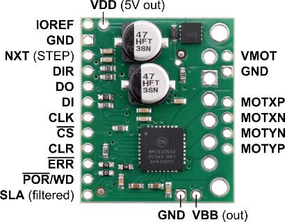
The layout has holes, pitch 2.54 mm, for mounting of goldpin connectors or screw connectors. Connectors included for self-soldering.
| Pin | Type | Description |
|---|---|---|
| UMOT | IN | The motor supply voltage from 6 to 30 V. There is a protection against reverse polarity. |
| VBB | OUT | The output voltage of the motor with protection against reverse polarity. |
| GND | The ground of the system. | |
| MOTXP | OUT | Output to connect motor PLUS coil X. |
| MOTXN | OUT | Output to connect motor MINUS coil X. |
| MOTYP | OUT | Output to connect motor PLUS coil Y. |
| MOTYN | OUT | Output to connect motor MINUS coil Y. |
| VDD | OUT |
Regulator output voltage of 5 V. Can be used to power the logic part through the adjacent pin IOREF if the module will work with circuit 5 V. The maximum output current depends on input voltage UMOT:
|
| IOREF | IN | All output pins except SLA pulled up to the voltage specified on the output IOREF. Therefore, this voltage should be equal to the operation voltage of the maincircuit, for example, when dealing with operating from 5 V Arduino Uno, the IOREF should be 5 V. |
| NXT | IN | One pulse on the specified pin STEP causing one step of the motor in the direction selected by making the appropriate logic state on the output DIR. The slope responds to the driver can be selected via the SPI bus, the default is rising edge. |
| DIR | IN | The choice of the direction of rotation of the motor through the low and high. The direction may also be adjustable via the SPI bus. |
| To | OUT | Output data (MISO) of the SPI bus. |
| DI | IN | Input data (MOSI) of the SPI bus. |
| CLK | IN | Line clock the SPI bus. |
| CS | IN | Select device (chip select) in SPI mode. For operation of the module, you must specify the status low. |
| CLR | IN | The system reset. The provision of high position causes the reset of internal registers. |
| ERR | OUT | The output indicates the error via the emergence of low position. Detailed error information can be read using the SPI bus. |
| SR/WD | OUT | The output generates a signal in a low state, which can be used as reset for the other side. |
| SLA | OUT | Analog output from 0 to 5V, for which the signal proportional to the voltage level of the back-EMF of the motor. Has a low-pass filter. |
|
Attention! The connection and disconnection of the motor while the driver is turned on can damage the system. |
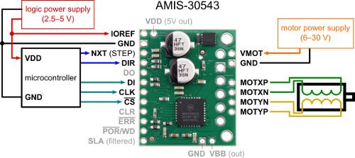
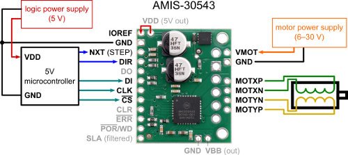
Example of the minimum connection
To output the IOREF should be the voltage you are working with digital inputs and outputs. In order to rotate the motor one step, you must specify the NEXT output state as high (logical unit), another sequence of zeros and ones moves the motor one step, etc. Choice of direction is accomplished by depositing on the output DIR (e.g. high - turn in a clockwise direction, low - counterclockwise direction). Other functions, such as maximum current or the permissions are set using the SPI bus.
Example of minimum connection for voltage of 5 V
In this case, IOREF can connect with the neighboring terminal VDD. Further part similar to the previous paragraph.
|
The product is compatible with Arduino |
Heat
The board was designed so that it could conduct heat at a constant current consumption of about 1.8 A per coil. If the current is much higher, use an externalheatsink to which the you can usethermoconductive glue.
Useful links |
