Specification
- Supply voltage: 3 V to 5 V
- Voltage of the pins: 3 V to 5 V
- Three axes: X, Y, Z
- Communication interface: I2C (TWI), SPI
- The bus address: 0x18 or 0x19 (selected with SDO pin)
- Resolution: 10 bits
- 3 additional analog inputs for reading I2C
- Measuring ranges (configurable):
- ±2 g, ±4 g, ±8 g, ±16 g
- Pins: goldpin connectors - 2.54 mm pitch (strap included in the kit for self-soldering)
- 4 mounting holes with diameter: 2 mm
- Board sizes: 25,4 x 17,8 mm
- Weight: 1.5 g
Description
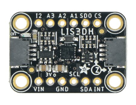
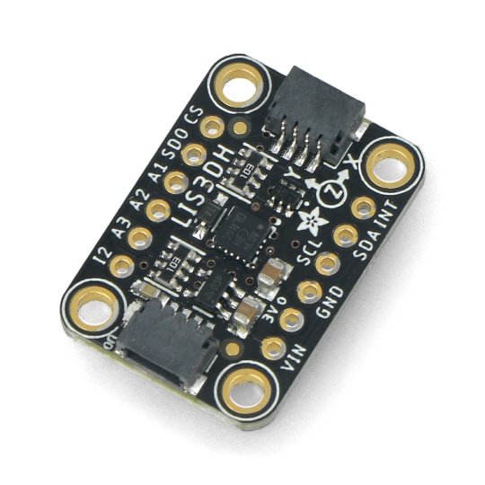
Sensor for measuring acceleration in three axes: X, Y, Z in the range of ±2 g, ±4 g, ±8 g / ±16 g. For communication with the central unit is the popular I2C or SPI bus. The module has necessary for the correct operation of the system, passive elements. Pins are holes for self-soldering of the goldpin connectors - 2.54 mm pitch (included) to connect the sensor viawires or to directly attach into the breadboard. The module also has a STEMMA QT connector that can be used to connect the sensor to the controller without soldering.
|
The product is compatible with Arduino A detailed description along with sample code, can be found inthe user guide. |
Pins
The sensor has pins for mounting the connectors of goldpin type - pitch of 2.54 mm, the strap is in the set for self-assembly. The board also has a STEMMA QT connector, which is an alternative connection method.

| Pin |
Description |
|---|---|
| Vin | The module's supply voltage ranging from 3 V to 5 V. |
| GND | The ground of the system. |
| 3Vo | Regulator's output of 3.3 V with the current of 100 mA. |
| SCL | Clock line of the bus I2C (TWI) SPI |
| SDA | The data line of the I2C bus (TWI) / CFI (MOSI) |
| SDO |
The address selection of the I2C bus:
|
| CS |
Selection of I2C / SPI. Pin not connected or connected to a high status, selects the I2C communication, connected to low status, it selects the SPI communication. |
| INT |
Programmable interrupts, the details inthe documentation. |
| A1, A2, A3 |
Analog pins to read the I2C bus, the details inthe documentation. |
Useful links |


