


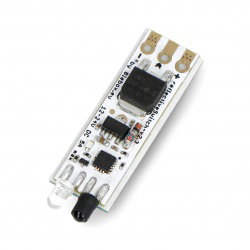

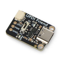

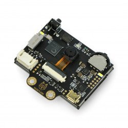
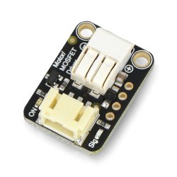


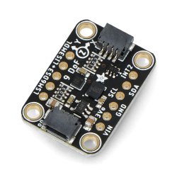


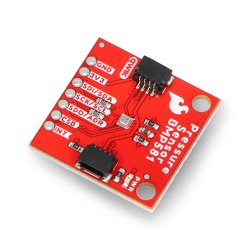

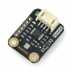

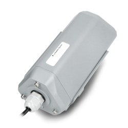

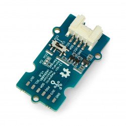


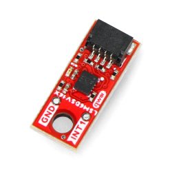


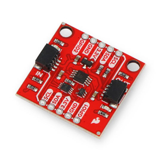


The Qwiic Power Switch from SparkFun allows you to more efficiently manage devices with Qwiic connectors. The switch module allows you to save power by selectively turning off selected devices. The Qwiic Power Switch has I2C bus isolation, which allows you to combine 100 kHz and 400 kHz I2C devices on the same bus. The module has been extended with additional GPIO pins that can be used to control other components in the project, and two Qwiic connectors allow for quick connection of peripherals.
The Qwiic Power Switch from SparkFun allows you to more efficiently manage devices with Qwiic connectors. Many Qwiic modules, especially high-power ones, draw power even in standby mode. The switch module solves this problem by allowing you to turn off your devices, thus saving energy and extending battery life. The Qwiic Power Switch has I2C bus isolation, which allows you to connect 100 kHz and 400 kHz I2C devices on the same bus, so you can avoid slowing down communication with faster devices. The module has been expanded with additional GPIO pins , which can be used as inputs or outputs to control other components in the project. Two Qwiic connectors allow you to quickly connect peripherals without having to solder connectors and wires .
The manufacturer has provided an Arduino library and a user guide for beginners.
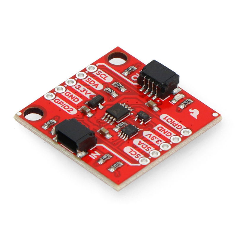
Qwiic Power Switch - power switch - SparkFun PRT-26784.
Qwiic Power Switch.
The integrated circuit supports voltages from 2.3V to 5.5V, for compatibility with the Qwiic Connect system it is recommended to limit the input voltage to 3.3V .
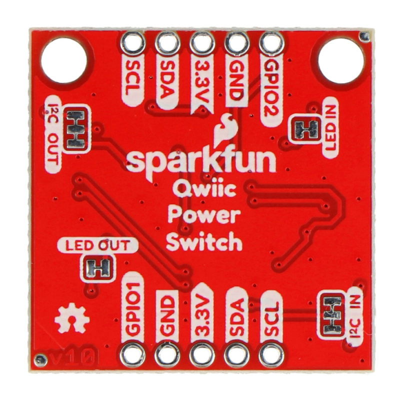
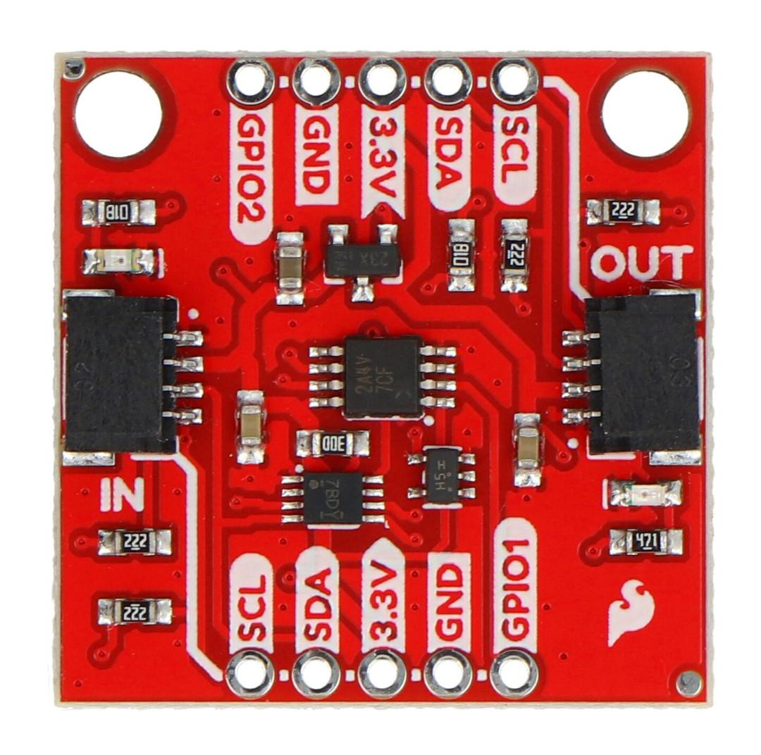
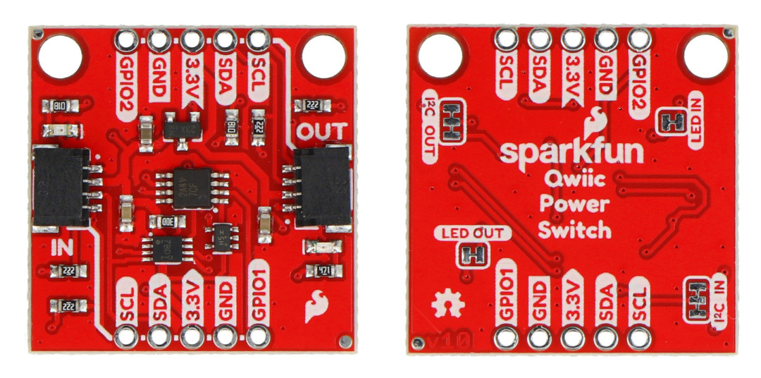
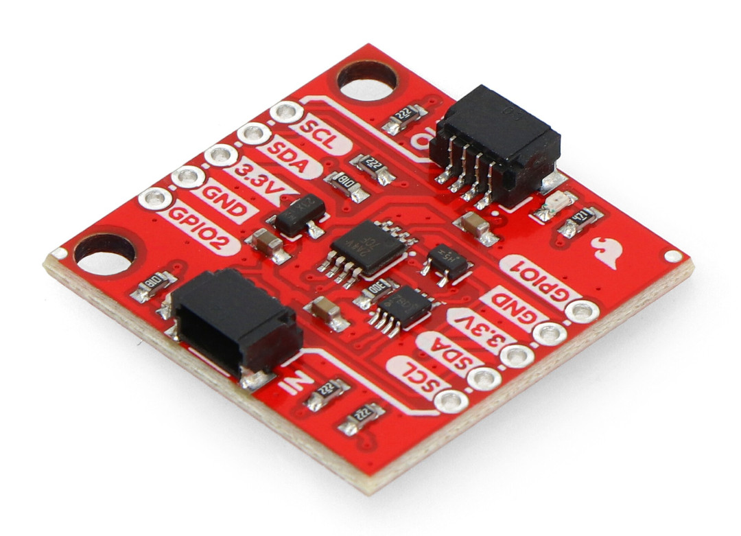
The button module has two Qwiic connectors on the board. There are also solder pads with the following pins:
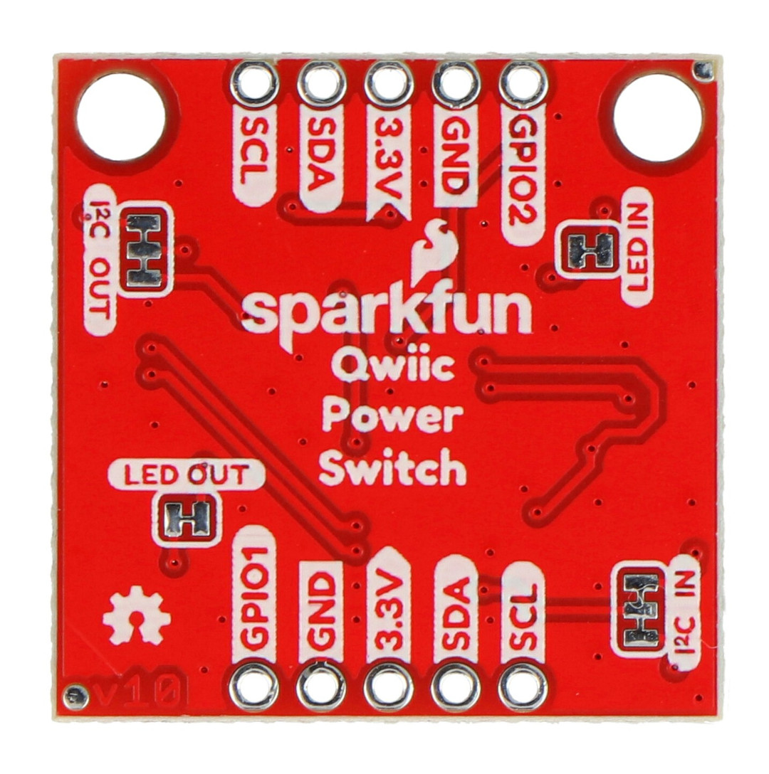
Qwiic Power Switch Pinout.
Qwiic Power Switch - SparkFun PRT-26784.
Useful links |
| Voltage nominal | 3.3 V |
| Niebezpieczne | Component |
| Package width | 9 cm |
| Package height | 5 cm |
| Package depth | 0.3 cm |
| Package weight | 0.003 kg |
Be the first to ask a question about this product!
Product Information
The product is a component intended for further assembly/prototyping. It does not constitute a standalone finished product within the meaning of product safety regulations.
Dane GPSR
Country of Origin: United States
Manufacturer Contact Details: SparkFun Electronics 6333 Dry Creek Pkwy, Niwot, CO 80503, Stany Zjednoczone
EU Marketer Contact Details: BOTLAND B. DERKACZ SP. K. Gola 25A - 63-640 Bralin