Description
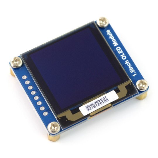
OLEDwhite display with a diagonal of 1.5" and a resolution of 128 x 128 px. Screen-based driver SSD1327 works with voltages of 3.3 V and 5 V, communication via SPI or I2C.
|
The manufacturer provides auser manual. |
Connection
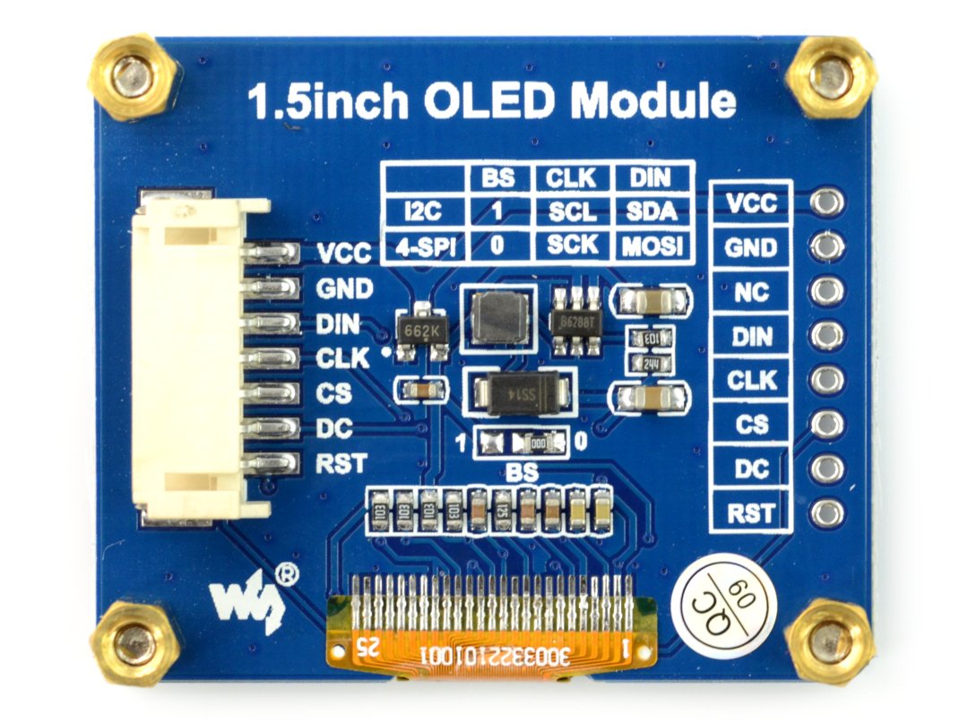
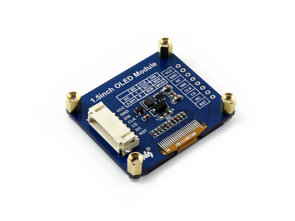
Module has 7-pin connector and holes for soldering connectors, raster 2.54 mm, communicates via SPI or I2C. Description of the specific outpus is given in the table.
| Pin | Symbol | Description |
|---|---|---|
| 1 | VCC | Supply voltage from 3.3 V to 5.0 V. |
| 2 | GND | The ground of the system. |
| 3 | DIN | Data line of SPI / I2C. |
| 4 | CLK | Clock line of SPI / I2C. |
| 5 | CS | Select the device SPI bus, activated by low state. |
| 6 | DC |
Select the operating mode - low state means the transmission of commands, high state meand the transmission of data. |
| 7 | RES | Reset system is activated by the low state. |
Setting
The choice bus is carried out with a jumper BS0 and BS1, which are on the back of the board. By default the display is in 4-wire SPImode. For details, see the table below.
|
Mode work |
Pin BS0 |
Function CS |
Function DC |
Function DIN |
Function
CCS |
|---|---|---|---|---|---|
| 4-wire SPI | 0 | Chip Select | Data / commands | MOSI | SCLK |
| I2C | 1 | NC | i2C address selection | SDA | SCL |
Jumper to select mode of operation is in the center of the module is BS.
|
The product is compatible with Arduino The manufacturer providesthe sample codefor users ofArduino. |
Specification
- Working voltage: from 3.3 V to 5.0 V
- Driver:SSD1327(documentation)
- Communication: SPI / I2C
- Mode selection by means of a jumper BS
- Display type: OLED
- Diagonal: 1.5 in"
- Screen resolution: 128 x 128 px
- Color: white
- The viewing angle of above 160°
- Dimensions: 44,5 x 37 mm
Useful links |


