Raspberry Pi relay control
Operating the relay with the Raspberry Pi has several important advantages. For example, we can program the control of electrical devices in the house and thus create the basic functions of an intelligent building.
In this example we will use it:
- Raspberry Pi 3 model B with Raspbian system
-
RM2 relay module with 5V 10A/125VAC optoelectronic isolation
Connection
The two devices shall be combined as shown in the table below
| GPIO Raspberry Pi | Relay |
|---|---|
| 5 V | VCC |
| GND | GND |
|
GPIO 1 (any pin can be used) |
IN1 |
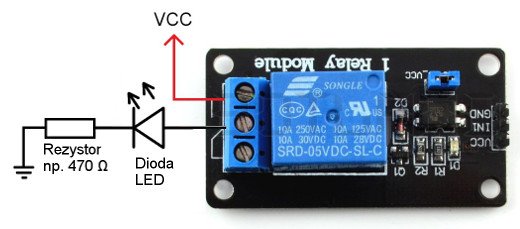
We connect any device we intend to control to the relay contacts, e.g. an LED bar. In the example we will use an ordinary diode with separate power supply. The power supply for the diode is connected via the relay contacts:
Operation
To use the GPIO pins in Raspberry we need a library that allows us to do so. For this we will use the wiringPi library. Description how to download and install it can be found here. Just copy the next commands. Finally, to check the correctness of the installation, type in:
-
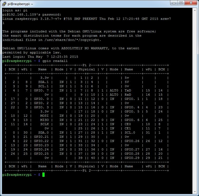
gpio readall
After this command we should see the table below:
Now we will write a simple program. We create the led.c file
-
nano led.c
The file should contain the following program:
#includeint main (void) { wiringPiSetup (); int pin = 1 ; pinMode (pin, OUTPUT) ; while(1){ digitalWrite (pin, HIGH) ; delay (1000); digitalWrite (pin, LOW); delay (1000); } return 0 ; }
Then save the changes to the file and close it. To compile the created file we use the command:
-
gcc -Wall -o indicator led.c-lwiringPi
To start the program, enter:
-
sudo ./led
The program alternately turns on and off the diode every 1 second. Thanks to this project we can understand the basic operation of GPIO in the Raspberry Pi and the use of relays.


