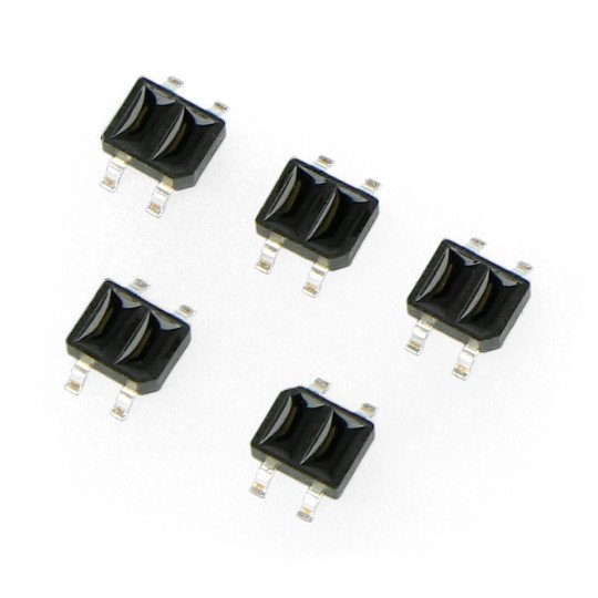
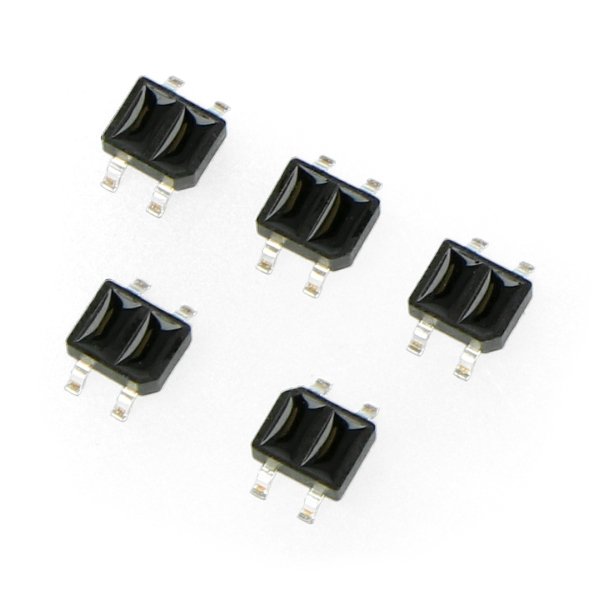
Specification of the optocoupler:
- The maximum voltage of the IR LED: 5 V
- The maximum current of the IR LED: 50 mA
- The maximum collector-emitter voltage: 30 V
- Maximum collector's current: 20 mA
- Case soldered on the surface (SMD)
Details inthe documentation.
Product description: Sensor reflective optocoupler KTIR0711S
The sensor sends a beam of radiation through the IR transmitter, then measures the intensity of the light reflected through phototransistor. The output is a voltage signal dependent on the light intensity falling on the detector. The more light will be reflected and get to photodetector, the higher wil be the output voltage. As the light is reflected better by the bright surface (dark surface absorbs it), the voltage will be higher on a white material.
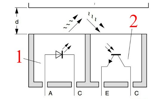 1. IR transmitter, 2. Detector (phototransistor).
The use of reflective sensor
The sensors are readily used by designers of Line Follower robots to detect lines, as well as in the minisumo construction where it is used to detect the edges of the ring. As, in these cases, detected are the extreme values (to distinguish black from white - intermediate values are not important), the sensor can be located higher above the surface than the documentation indicates. From our experience, we can tell that with appropriate selection of resistors, sensors correctly distinguish the black insulating tape from the white background from a distance of about 0.5 cm.
The advantage of the sensor are small size and light weight. It lacks, however, the protective case (which can be found in the CNY70 sensor) so when it is maximally close to the surface, it is not working properly. Therefore, you should take care of the appropriate setting of this parameter.
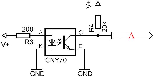
Connection example KTIR0711S
The sensor consists of two main parts: a detector in the form of phototransistor, and transmitter as an infrared led. For the transmitter not to be damaged, you should limit its current (max. 50 mA), and, consequently, the infrared radiation power. This is done through the resistor connected in series (R3). For the proper operation of the phototransistor, necessary is the pulling-up resistor (marked on the figure as R4). The propert values must be selected usingthe documentation(example on the picture below).
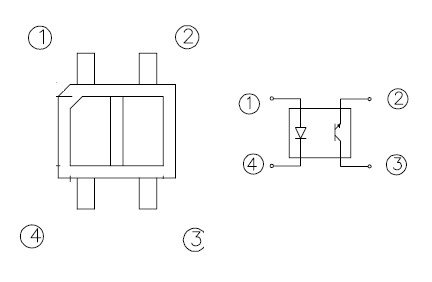 1 - Anode, 2 - Emitter, 3 - Collector, 4 - Cathode.
Useful links |
