Description
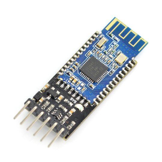
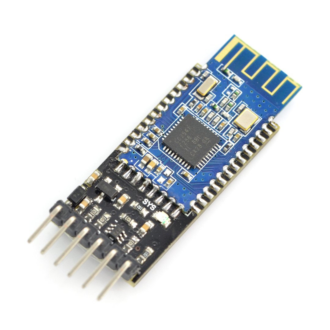
A simple system of communication based on the Bluetooth HM-10 v4.0 BLE module. Communication is via the serial UART using AT command. It has a built-in voltage converter so it can work in the standard 3.3 V and 5 V.
|
The module has a built-in converter of 3.3 V/5V so the built-in goldpins can communicate with voltage of 5 V. |
Specification
- Supply voltage: from 3.3 V to 5 V, connected to VCC pin
- Current consumption: up to approx. 20 mA
- Transmitting power: max. + 6 dBm
- Range: up to 10 m
- The password for pairing: 000000
- Standard: Bluetooth 4.0 BLE
- Communication: UART (RX, TX)
- Pitch of pins: approx. 1.5 mm
- Small size: 40 x 15 mm
Connection
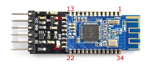
To start the module, you must connect the supply voltage to a pin marked VCC. The module is detected via the computer as unknown system or HMSoft to pair both devices, you need to enter the password:000000. In the system displayed will be a virtual COM port, through which, using any terminal, it is possible to transmit data. The board has pins of the serial interface UART - pins TX and RX that you can connect, for example, withArduinoor with a PC viaUART converter.
| Pin | Description |
|---|---|
| 1 | TX - UART output. |
|
2 |
RX - UART input. |
|
3 |
CTS - UART interface. |
|
4 |
RTS - UART interface. |
|
5 |
NC - Not connected. |
|
6 |
NC - Not connected. |
|
7 |
NC - Not connected. |
|
8 |
NC - Not connected. |
|
9 |
NC - Not connected. |
|
10 |
NC - Not connected. |
|
11 |
RST - Reset. |
|
12 |
VCC - 3.3 V Power supply |
|
13 |
GND - Ground |
|
14 |
GND - Ground |
|
15 |
USB_D - USB interface. |
| 16 | NC - Not connected. |
|
17 |
NC - Not connected. |
|
18 |
NC - Not connected. |
|
19 |
NC - Not connected. |
|
20 |
USB_D+ USB interface. |
|
21 |
GND - ground of the system. |
|
22 |
GND - ground of the system. |
|
23 |
PIO2 Programmable input / output. |
|
24 |
PIO1 Programmable input / output. |
|
25 |
PIO2 Programmable input / output. |
|
26 |
PIO3 Programmable input / output. |
|
27 |
PIO4 Programmable input / output. |
|
28 |
PIO5 Programmable input / output. |
|
29 |
PIO6 Programmable input / output. |
|
30 |
PIO7 Programmable input / output. |
|
31 |
PIO8 Programmable input / output. |
|
32 |
PIO9 Programmable input / output. |
| 33 | PIO10 Programmable input / output. |
|
34 |
PIO11 Programmable input / output. |
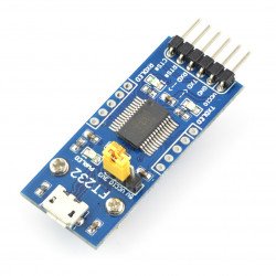
Communication can be tested by the pairing the module with the computer and connecting the board using the FTDI converter. In two terminal windows, you should select the appropriate communication ports and also specify the transmission rate of 9600 bps. If the configuration is correct, the text sent from one terminal will appear on the second.
The configuration of the module is via the popular AT commands to enter this mode, you need to connect the VCC pin to 3.3 V. Examples of the commands are:
- AT - connection testing, in return we get "OK".
- AT+VERS? - it shows the software version.
The instruction needs to be sent without a sign of line ending. More commands can be found in the documentation.
Useful links |
