


Control of LEDs by WiFi using ESP8266
The example shows how to send data via web page to ESP8266 module using Arduino. The program controls LEDs connected to Arduino board.
In the example the following elements were used:
- Computer equipped with WiFi card
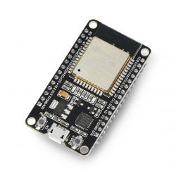
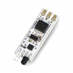
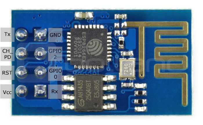
ESP-01 connection from Arduino
For communication between the WiFi module based on ESP8226 and Arduino board there is serial interface UART. In this case its software version will be used, hardware UART, i.e. pins 1 and 0 will remain at your disposal. The circuits should be connected, e.g. by means of female/male wires in the following way:
| Pin ESP8266 | Pin Arduino |
|---|---|
| Tx | 2 |
| Rx | 3 |
| Vcc | 3,3 V |
| CH_PD |
3,3 V |
| GND | GND |
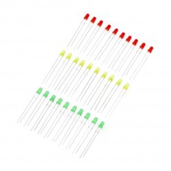
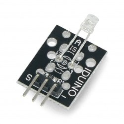
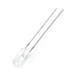
Connect the LEDs to pins 11, 12 and 13 of Arduino through a current limiting resistor. The brightness of the LED depends on its value, too little resistance can damage the diode, if it is too big it will not glow. We suggest to choose the resistance value from 220 Ω to 1.5 kΩ.
Program for Arduino
The following code was used in the example:
#include///To connect the library to the UART software interface SoftwareSerial esp01(2,3); // UART software interface initialization: 2-RX (connect to Tx ESP module); 3-TX (connect to Rx ESP module) void setup() { Serial.begin(9600); // Initialization of the hardware UART interface at 9600 bps - for communication with a computer via USB esp01.begin(9600); // UART software interface initialization at 9600 bps - for communication with the ESP module pinMode(11,OUTPUT); // setting pin 11 as input for LED 1 digitalWrite(11,LOW); // low state on pin 11 - LED 1 disabled by default pinMode(12,OUTPUT); // setting pin 12 as input for LED 2 digitalWrite(12,LOW); // low state on pin 12 - LED 2 off by default pinMode(13,OUTPUT); // setting pin 13 as input for LED 3 digitalWrite(13,LOW); // low state on pin 13 - LED 3 disabled by default //Send in the ESP module's initialization commands sendData("AT+RSTrn",2000); //reset of module sendData("AT+CWMODE=2rn",1000); // set in Access Point mode sendData("AT+CIFSRrn",1000); //receive an IP address (default 192.168.4.1) sendData("AT+CIPMUX=1rn",1000); //enabling multiple connection mode sendData("AT+CIPSERVER=1,80rn",1000); // setting the server on port 80 } void loop() { if(esp01.available()) // check if the module has received the data { if(esp01.find("+IPD,")) { delay(1000); // waiting for the data buffer to fill // reading the connection ID int connectionId = esp01.read()-48; //read ASCI value: subtracted 48 because read() returns the decimal value of ASCII at item 48 esp01.find("pin="); // find the phrase "pin=" and set the "cursor" there int pinNumber = (esp01.read()-48)*10; // download the first digit, e.g. for pin 13, the first digit is 1, multiply it by 10 pinNumber += (esp01.read()-48); //pick the second digit, e.g. for pin 13, the second digit is 3, it should be added to the previous result digitalWrite(pinNumber, !digitalRead(pinNumber)); // change of state of selected pin // closing the connection String closeCommand = "AT+CIPCLOSE="; closeCommand+=connectionId; // Connection ID read at start closeCommand+="rn"; sendData(closeCommand,1000); // send commands to terminate the connection } } } /* * Function to send commands to ESP01 * Parameters: * command - command to be sent * timeout - time to answer */ String sendData(String command, const int timeout) { String response = "" esp01.print(command); // send command to ESP01 long int time = millis(); while( (time+timeout) > millis()) { while(esp01.available()) //If there's any data from the module, then it's read { char c = esp01.read(); // reading the next character response += c; } } Serial.print(response); return response; }
HTML code for sending data
Copy the code below and, using e.g. the system Notepad, save it with the .html extension.
|
LED Control via ESP8266 |
The program also uses the JQuery library. It should be downloaded and saved in the directory where the above .html file is located.
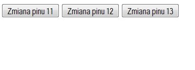
Starting the program
At the beginning, it is necessary to connect with the module as an access point (similarly to e.g. a wireless router). After establishing the connection, open the created website using any browser. Using one of the three buttons you can light or turn off the diodes.