Arduino - the exits
Table of contents
Special functions
In addition to the standard role of digital inputs/outputs, the Arduino outputs have some special functions. These are among others: outputs of hardware communication interfaces, analog outputs or timer outputs (counters). For each of them Arduino has a library, which makes using them very easy. Below is a description of the most popular peripherals:
- Serial interface (UART) - Two lines are used for transmission: RX - receiver and TX - transmitter. The interface is very simple in configuration, allows for data exchange with a computer, or support of digital devices such as Bluetooth module orMaestro server controller. Sometimes it is marked as USART. The letter S indicates that the data is sent in a synchronous way, i.e. for transmission, apart from TX RX, one more line is needed - a clock line (CLK).
- External interrupts - Allow immediate handling of external events, signalled by a logical signal. Events can be triggered by a descending or ascending slope or any logical change. When an event occurs, the processor will immediately interrupt all previous operations and start executing the code fragment related to the interrupt handling.
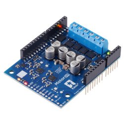
- PWM outputs - Pulse Width Modulation. With these outputs, the user can generate a hardware-based signal (without occupying the processor) with the set fill level. This function is used e.g. to control the speed ofDC motors using Motor Shield orany motor controller (e.g. TB6612). It also allows tocontrol the position of servers.
- SPI interface - Serial bus running synchronously. Three outputs are used for communication: MISO, MOSI, SCK. It is characterized by high transmission speed, that is why it is used to operate fast devices (e.g. EEPROM memory, A/C, D/A converters). It is also used to communicate with some displays and sensors.
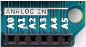
- Analogue inputs - Outputs enabling operations on an analogue signal. They are connected to a built-in analog-to-digital converter. Each has a 10-bit resolution (1024 different values). With analog inputs, the user can operate different sensors (e.g. accelerometers oroptical sensors), orcreate his own voltagemeter.
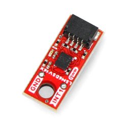
- TWI - I2C - Another popular serial synchronous communication interface. It requires two communication lines: data and clock (CLK). With I2C the user can operate e.g. MEMS sensors ( MinIMU-9).
POWER connector outputs
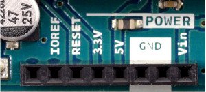
Arduino also has power connectors. Below is a description of the most important of them.
- VIN - Input voltage (used when external power supply is selected). User can use this pin or DC (power jack) connector to power the system. Recommended power supply voltage range 7V-12V
- 5V - 5V regulator output. Using this output the user can supply his own systems working with 5V voltage. Please note that connecting an external power source (above 5V) to this pin can lead to permanent damage to the module.
- 3V3 - 3.3V regulator output. Maximum current 50mA. Using this output, the user can supply his own systems working with 3.3V. Connecting a device with higher current consumption or connecting an external power source to this pin can permanently damage the system.
- GND - ground potential.
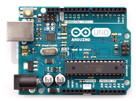
Description of module outputs on the example of Arduino Uno.


