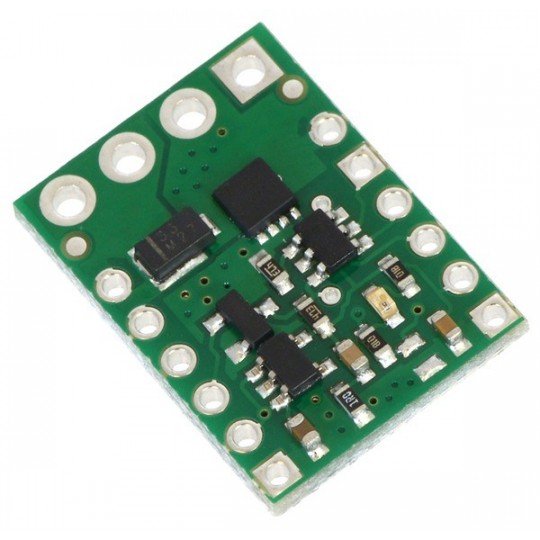
Specification
- Load voltage: up to 30 V
- Load current: up to 15 A
- Supply voltage of the digital part: 2.5 to 16 V
- Dimensions: 21 x 15,2 mm
- Weight: 1.2 g (without connectors)
- The set includes:
- module and connectors for self soldering
Description
The module processes the radio signals from standard amateur transmitters to digital signals of on/off type. The system has the unipolar low-sideMOSFET transistor which allows to control the devices with a supply voltage of up to 30 V and current consumption of up to 15 A. The set includes: module with goldpin and ARK connectors, for self-soldering.
Connection
Supply voltage of the logic part connected to the VIN and GND pins. Thanks to the integrated voltage regulator, the chip can be powered with any voltage ranging from2.5 to 16 V which allows you to directly connect 4 or 5-goal NiMh and NiCD packet. The supply voltage of the load of up to 30 V, should be connected to the external pins in the top part of the module, the load consuming the current of up to 15 A, to the internal pins - in accordance with the figure below. Detailed description of the pins, can be found inthe instructions.
The system measures the width of pulses from the RC receiver, connected to the RC IN pin and compares with the user-specified threshold (1700μs by default). If the threshold is exceeded, there will be an activation of switch. The module has the functions of the safe start which protects from unwanted activation.
The negative pole of the supply voltage must be connected to the GND pin (in the upper right corner of the system) and to the LOAD LOW pin. Four LOAD HIGH pins are internally connected, they must serve only for user's convenience - this means thay you can use any pin. Among these pins is the LED protecting the system. Applied MOSFET can deliver 15 A of current during the activation with the voltage of 5 V. Details in theinstruction and on the module's scheme.
Pins
| Name | Description |
| VIN | Supply voltage of the logic part: 5 V - 16 V |
| GND | The ground of the system |
| RC IN | RC signal input |
| GOOD | Indicator of the correct radio signal (10 to 330 Hz and 0.5 - 2.5 MS fill) |
| OUT | An indicator indicating if the MOSFET transistor is currently on. |
|
LOAD LOW LOAD HIGH |
Output pins, detailed description inthe instructions |
Useful links |


