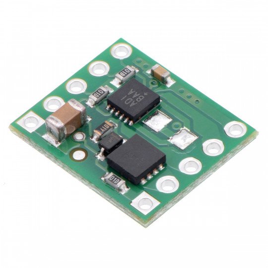
Description: MAX14870 - single channel 36V/1.7A motor controller
The module based on the MAX14870 Instruments system allows to control one DC motor. The motor can be powered from 4.5 V to 36 V with a continuous current draw of up to 1.7 A, temporary (for a few seconds) to 2.5 A. Before use, we recommend to read thedocumentation ofthe MAX14870.
Polol MAX14870 motor controller specifications
- Number of channels: 1
- Supply voltage: 4.5 V to 36 V
- Continuous current per channel: 1.7 A
- Maximum instantaneous current per channel: 2,5 A
- Maximum PWM signal frequency: 50 kHz
- Reverse power supply protection
- Dimensions: 15.5 x 13.0 mm
- Weight: 5 g (without connectors)
- Included module and goldpin connectors
Connecting the motor controller
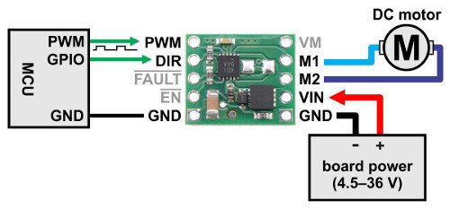
In a typical application, it is enough to connect two control lines: DIR direction selection and PWM speed control. By default, the PWM signal on the board is pulled up to ground by a 100 kΩ resistor, so the controller is switched off. If there is no need to use speed control, a high state (logical one) must be specified on the PWM output.
The EN or ENABLE output disconnects the motor outputs. If the high state is given, the M1 and M2 outputs are in high impedance state. The EN is pulled to ground by a 100 kΩ resistor, which means that the circuit is switched on by default.
| EN | PWM | DIR | M1 | M2 | Mode of operation |
|---|---|---|---|---|---|
| 1 | X | X |
high impedance |
high impedance |
disconnected outputs idle |
| 0 | 1 | 0 | GND | VIN | forward revolutions |
| 0 | 1 | 1 | VIN | GND | backwards |
| 0 | 0 | X | GND | GND |
braking outputs connected to the ground |
1 - high state, 0 - low state, X - unconnected output
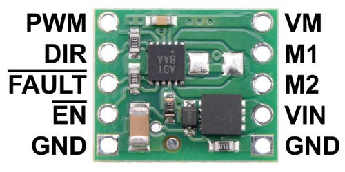
MAX14870 controller outputs
| PIN | Description |
|---|---|
| Vin | Motor supply voltage from 4.5 V to 36 V. |
| GND | The mass potential of the system. |
| M1 | Outputs + to connect the motor outputs. |
| M2 | Outputs - to connect the motor outputs. |
| DIR | Logical input defining the direction of engine rotation. |
| PWM | Logical input for speed setting. A PWM signal must be connected to this output. Default is low. |
| EN | Logical input that switches the system to the sleep state when low state is given. Default is high state. |
| FAULT | Logical output indicating error in low state. Not connected by default. |
Current limitation
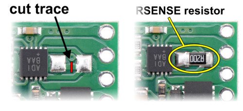
The system has the ability to limit the motor current. To do so, cut the path as shown in the drawing:
then solder the resistor in SMD 1206 housing. 100 mΩ resistor will limit current to 1 A, 200 mΩ to 0.5 A etc. See thedocumentationfor details.
Video
Film describing the operation of the H-bridge - direct current motor controller.
Useful links |


