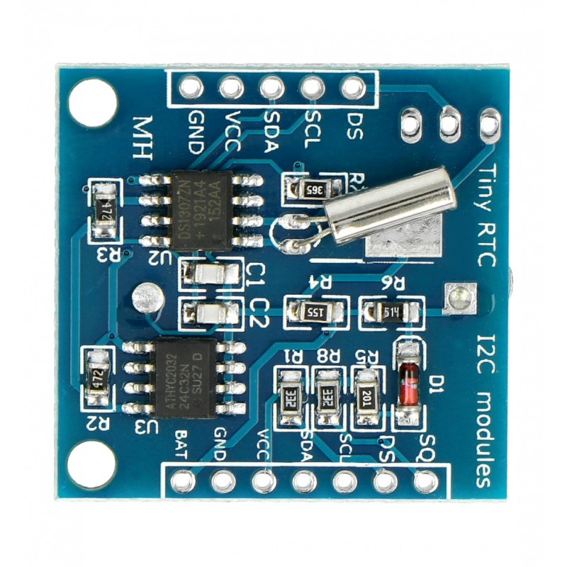


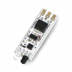


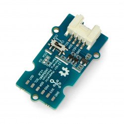


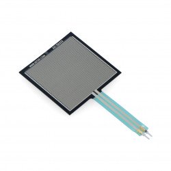


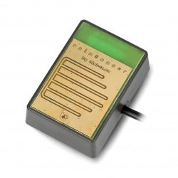


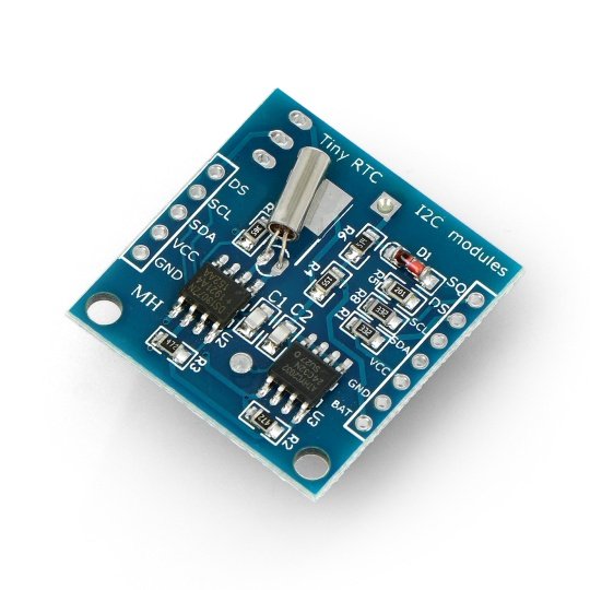


Module with real time clock and backup battery. It allows you to read the time in hours, minutes, and seconds, date: month, day, year. It has 32 KB of EEPROM. The communication interface is an I2C bus. It is the output of the temperature sensor DS18B20.
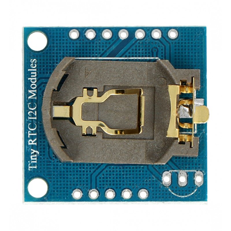
Module with real time clock and backup battery (battery included). It allows you to read the time in hours, minutes, and seconds, date: month, day, year. It has 32 KB of EEPROM. The communication interface is an I2C bus(SDA and SCL), data update frequency is 1 Hz (1 second). It is the output of the temperature sensorDS18B20.
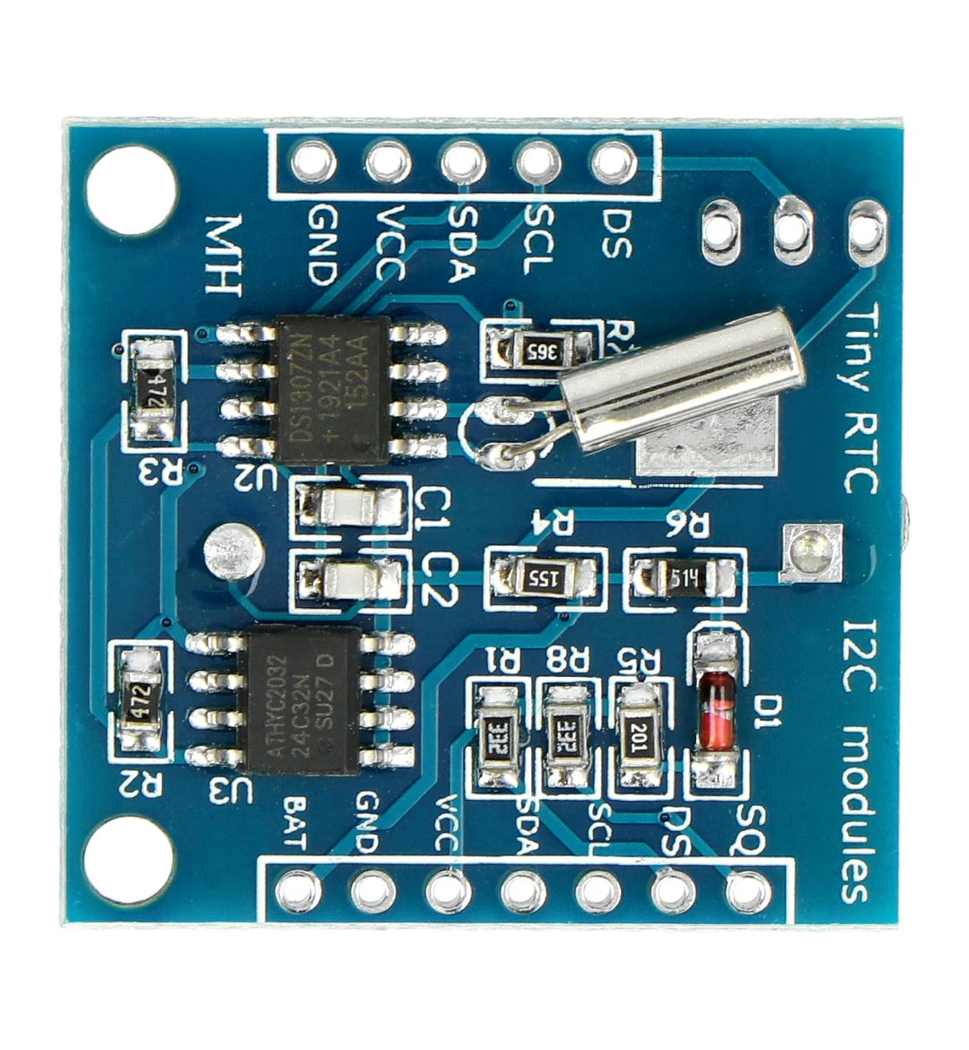
The supply voltage of5 Vis connected to the terminal marked with the same symbol. The I2C bus must be connected to the outputs SCL- clock line andSDA - data line. PinSQis the output of a rectangular signal with the selected frequency (see page 3of the documentation).GNDis the ground system.
| Pin | Description |
|---|---|
| SQ | The output of the square wave signal. |
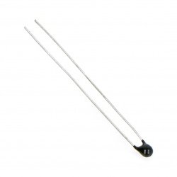
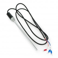
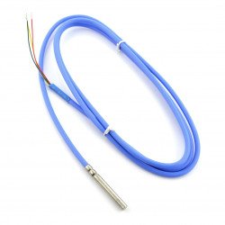
| DS | The output of the temperature sensor DS18B20. |
| SCL | Clock line of I2C interface. |
| SDA | Data line of I2C interface. |
| VCC | The supply voltage of 5 V. |
| GND | The ground of the system. |
| BAT | The battery output. |
Outputs are solder fields for soldering goldpin connectors- 2.54 mm raster (not included). Thanks to them, it is possible to connect the system with thebreakout boardor the main module (for example,STM32DiscoveryorArduino) viawires.
Useful links |
| Niebezpieczne | Component |
| Package width | 4.8 cm |
| Package height | 1 cm |
| Package depth | 6 cm |
| Package weight | 0.005 kg |
| Piotr
08/30/21 | Question: Good day Does Index: GRL-12507 work with 3.3V supply ? I ask because w/ documentation there is a chance. |
Answer: On page 9 of the documentation there is information about the recommended operating parameters of the module and the power supply is given in the range from 4.5 V to 5.54 V. We recommend a power supply within this range. | |

Product Information
The product is a component intended for further assembly/prototyping. It does not constitute a standalone finished product within the meaning of product safety regulations.
Dane GPSR
Country of Origin: China
Manufacturer Contact Details: SHEN ZHEN YOU MAI KE TECHNOLOGY COLTD 2 Floor,C Building,Mingxin Industrial Park,No.28,Hualong Road Longhua District, Shenzhen, 518109 China Phone: 8617724681799
EU Marketer Contact Details: BOTLAND B. DERKACZ SP. K. Gola 25A - 63-640 Bralin