- Sale
- SPECIAL OFFERS
Description
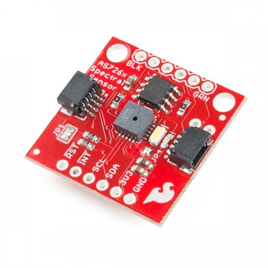
The module is equipped with a sensor of spectrum, i.e. the spectrum of visible light, allows you to measure and to characterize how different materials absorb and reflect light waves. It detects the wavelength range seen in the light of 450, 500, 550, 570, 600 and 650 nm, each with a 40 nm of full width of half of maximum detection. The sensor communicates using I2C and UART interface via AT commands. It has two connectors Qwiic, pitch of 1 mm and the connectors for soldering the goldpin strap of 2.54 mm(sold separately).
The board has a built-in LED with a power of 5700K, which is used to illuminate the objects. You can solder any LED operating at a voltage of 3.3 V.
Pins
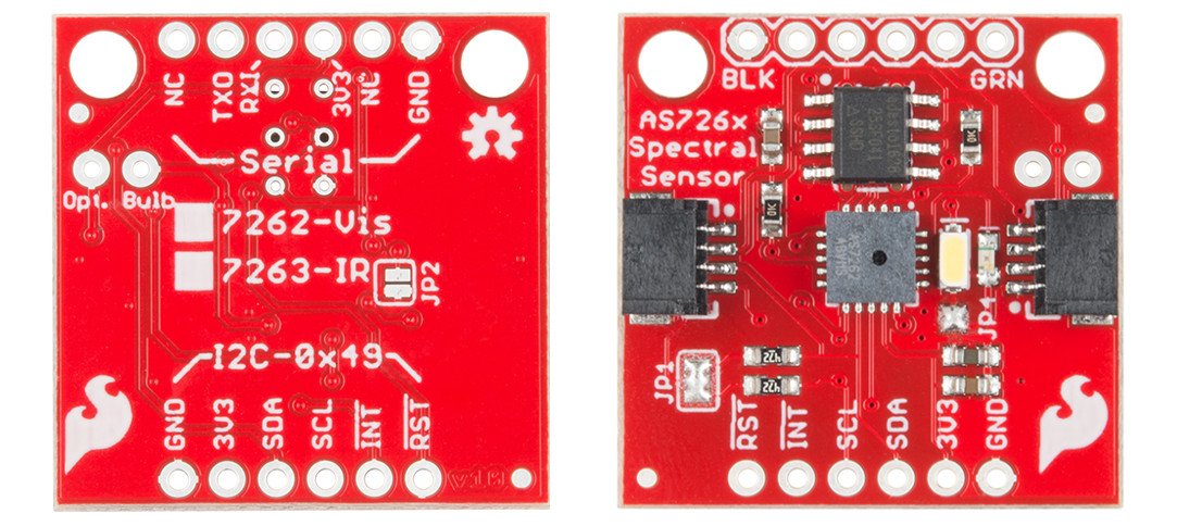
Module AS7262 has two communication interfaces: I2C and serial. The I2C interface is default. To use the serial interface, you must remove the tin located on jumper JP1 and put it on jumper JP2, located on the other side of the board. For serial communication with the computer, use a converter USB-to-Serial. On the board are two connectors Qwiic of 1 mm and output of 2x 6-pin for soldering the goldpin strap of 2.54 mm.
| Pin | Description |
|---|---|
| GND | The ground of the system. |
| 3V3 | Supply voltage is 3.3 V. |
| SDA | The data line of the I2C bus. |
| SCL | Clock line of the I2C bus. |
| INT | The external interrupt, the sensor sends a signal after finished measurement (optional pin) |
| RST | Reset |
| NC | Normally Closed |
| TX0 | UART interface - transmitter |
| RX1 | UART interface - receiver |
| 3V3 | Supply voltage of 3.3 V |
| NC | Normally Closed |
| GND | The ground of the system |
Specification
- Supply voltage: 2.7 V to 3.6 V
- 6 visible channels:450, 500, 550, 570, 600 and 650 nm, each with 40 nm of FWHM
- 16-bit ADC with digital access
- Programmable driver of LED
- Communication interface: I2C and UART
- Connectors:
-
- 2x Qwiic pitch of 1 mm
- 2x 6-pin lead, pitch of 2.54 mm
Useful links |


