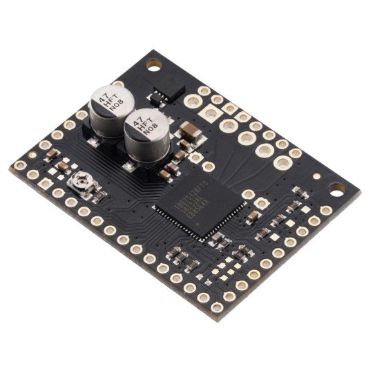
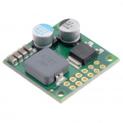
Description: TB67S128FTG - 44V/2,1A stepper motor controller - Polyol 2998.
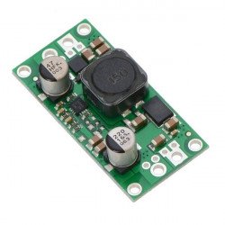
Stepper motorcontrollerwithToshiba TB67S128FTG chipwhichallows to adjust current limitation and step resolution up to 1/128. The chip cancontrolthe stepper motor using a device which allows to generate logical states, e.g. Arduino, Raspberry Pi. Powered from 6.5 V to 44 V,the maximum current consumption per coil is 5 A. The system used allows for the flow of up to 2.1 Acurrent without the use of a heatsink.
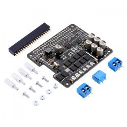
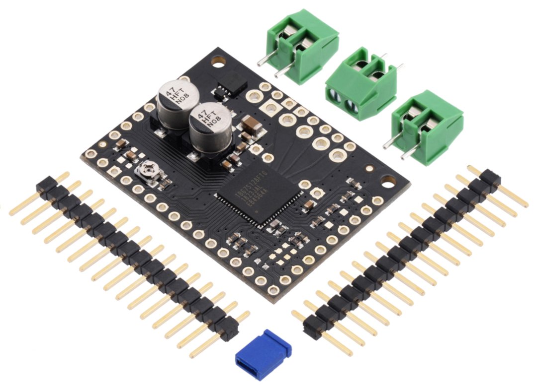
TB67S128FTG motor controller, self-mounting connectors are included.
|
The kit includes: module, screw connectors and goldpin strips for self-assembly. |
Connection of the TB67S128FTG motor controller
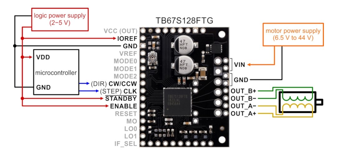
To control the stepper motor, connect the system as shown in the figure below.
Minimum diagram of connecting the controller with a microcontroller and a stepper motor.
Motor controller power supply
The controller requires a power supplyfrom 6.5 V to 44 Vsupplied to VIN and GND connectors. The selected power supply should be able to provide adequate current for the stepper motor. Output5 Vfrom the internal controller of the TB67S128FTGon the VIN connector. The output has a capacity of5 mAand can optionally be used to supply the adjacent IOREF pin. Four, six and eight-wire motors can also be operated with the controller if properly connected. SeeFAQfor more information.
|
Note! Connecting and disconnecting a motor while the controller is on can damage the system. |
Step resolution control
The layout allows you to select one of seven step resolutions. The resolution is set by specifying high or low state for each of the MODE inputs 1 / 2 / 3. Below is a table showing the possibility of setting the resolution of steps.
| MODE1 | MODE2 | MODE3 | Step resolution |
|---|---|---|---|
| Low | Low | Low | Full step |
| Low | Low | High | Half step |
| Low | High | Low | 1/4 step |
| Low | High | High | 1/8th step |
| High | Low | Low | step 1/16 |
| High | Low | High | 1/32 step |
| High | High | Low | 1/64th step |
| High | High | High | 1/128 step |
Engine control
The number of pulses given per CLK (STEP) pin corresponds to the number of steps made by the motor, the direction of rotation of the motor shaft is selected by the CW / CCW (DIR) pin. Both inputs have a pulled-down resistor that reduces 100 kΩ. If the CW / CCW pin is left disconnected, the motor will rotate in one direction.
The system has two inputs to control the power supply states: STANDBY and ENABLE, both must be high for the motor to operate properly. See thedocumentationfor more information.
Setting the current limit for Polol motor controllers.
TB67S128FTG controller specification
- Supply voltage: 6.5 V to 44 V
- Logical voltage: 2 V to 5.5 V
- Continuous current on the coil: 2,1 A
- A temporary coil current: 5 A
- Step resolution: full, 1/2, 1/4, 1/8, 1/16, 1/32, 1/64, 1/128
- Current limitation control: potentiometer, digital, SPI
- Reverse polarity protection
- Dimensions: 40.6 x 30.5 mm
- Weight: 5,7 g
The set includes
- TB67S128FTG controller module
- 2x goldpin16-pin strip
- 3x 2-pin screw connections
- Jumper
Useful links |
