Over 500,000 customers already trust us. With us you get:
same-day shipping for products marked “24h shipping”
our own service centre in Poland
30 days to return and free delivery in Poland from PLN 500
4.9/5 on TrustMate and 4.9/5 on Google (almost 4,000 reviews)
VAT invoice, leasing and instalments for businesses
For businesses
individual quote for larger quantities
VAT invoice
For schools and universities
orders based on requests for quotation
help with choosing kits for your lab
Send an inquiry - we reply quickly.

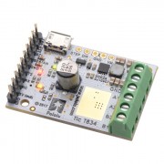
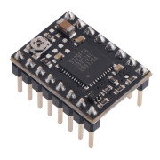
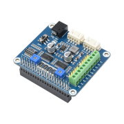
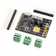
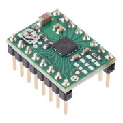
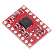
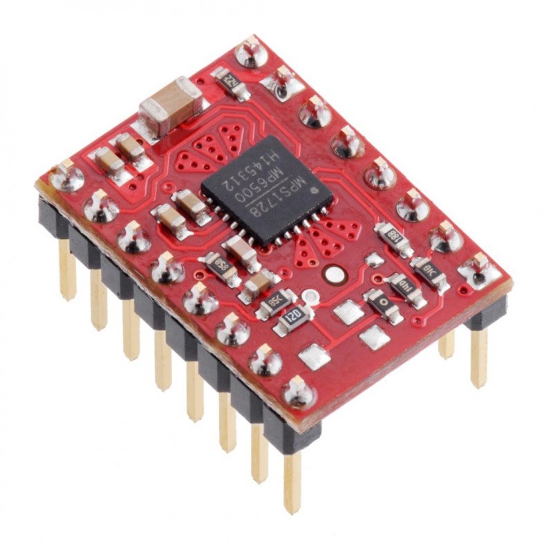
MP6500 Stepper Motor Driver Carrier, Digital Current Control (Header Pins Soldered) - Pololu 2969
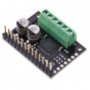
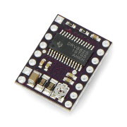
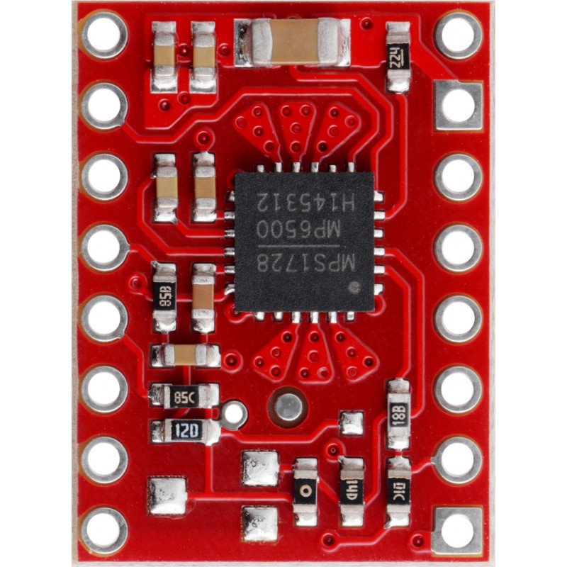
Stepper motor driver based on MP6500 chip. Powered by a voltage range from 4.5 V to 35 V, with a maximum current consumption of 2 A per coil. Maximum resolution: 1/8 step. The module allows up to 1.8 A of current to flow without a heat sink. Current control is performed digitally. Module in version with soldered goldpin connectors.
We could not load the price.
The promotional price does not combine with quantity discounts.
Product description: MP6500 - 35V/2A stepper motor driver - with digital current control - assembled - Pololu 2969
The chip allows you to control a stepper motor using a device capable of generating logic states such as Arduino, STM32Discovoery, Raspberry Pi or any microcontroller. Pololu module is characterized by very simple operation. In order to rotate the motor by one step, the STEP pin should be given a high state (logical one), the next sequence of zero and one will move the motor by another step, etc. The selection of the direction is performed by giving the appropriate state to the DIR pin (e.g. low state - clockwise rotation, high state - anticlockwise rotation). The driver also has the ability to select the resolution of motor operation.

Botland is an official distributor of Pololu electronics and robotics parts. Countless robots hold at least one component of this brand in their build. Our team guarantees that all Pololu products presented here are original.
Technical specification of the driver
- Supply voltage of the motor: from 4.5 V to 35 V
- Current: max. 1.8 A per coil (with cooling up to 2 A)
- Supply voltage of logic part: from 3.3 V to 5 V
- Simple control interface
- Operation in 4 different modes: full step, 1/2, 1/4 and 1/8
- Digital current regulation
- Protection against overheating of the circuit
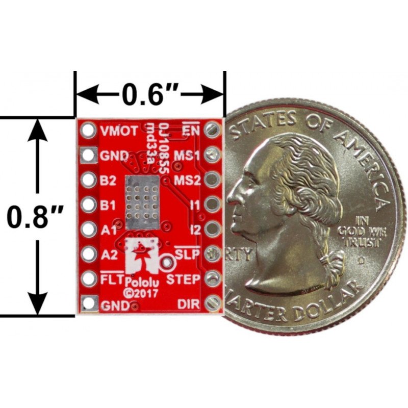
- Module dimensions: 20 x 15 mm
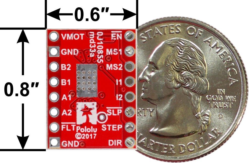
The module has soldered goldpin connectors. We also offer a version without connectors. |
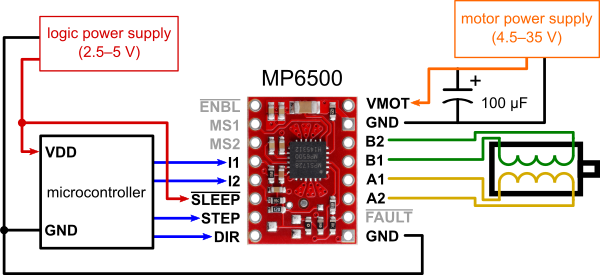
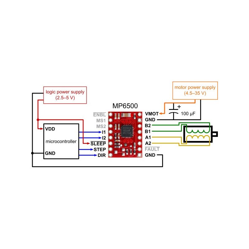
The figure shows the minimum connection of the controller. A resistor of +/- 100 µF should be placed between the motor power supply pin and ground.
Controller connection
To control a bipolar stepper motor, connect the system according to the drawing below. In case of controlling a unipolar motor, refer to the manual. If the nominal motor voltage is lower than required driver supply (4.5V), set the current limit digitally.
Power supply of the module
For supplying the logic part of the module a voltage in the range of 2.5 V to 5 V is required, which should be connected to the Sleep pin. The motor supply voltage from 4.5 V to 35 V is applied to the VMOT pin. The circuit can be used to control motors with a nominal voltage lower than the required 4.5 V. For this purpose, the maximum current consumption must be limited so as not to exceed the allowable motor current. For example, for a motor with a resistance of 5 Ω per coil and a current consumption of 1 A, the nominal supply voltage is 5 V. When supplied with 12 V, the current should be limited so that it does not exceed 1 A.
Caution! Connecting and disconnecting the motor while the controller is on can damage the system. |
Resolution and step size
The step size is selected using MS1, MS2 inputs. The possible settings are shown in the table below. The MS1 and MS2 inputs have an internal pull-down resistor (500 kΩ).
| MS1 | MS2 | Resolution |
|---|---|---|
| low | low | Full step |
| high | low | 1/2 step |
| low | high | 1/4 step |
| high | high | 1/8 step |
Other inputs
One pulse on the STEP pin causes one step of the motor in the direction selected by giving the corresponding logic state to the DIR pin. If the motor is to spin in one direction only, the DIR pin can be left disconnected.
The chip has two different inputs to control the power supply: SLEEP and ENBL their description can be found in the documentation. Note that the controller pulls both of these pins through internal 500 kΩ pull-down resistors. The default SLEEP state prevents the motor from running, a high state must be applied to it (it can be connected directly to a 2.5 to 5 V logic supply or it can be controlled by connecting to a digital MCU output). The default state of ENBL is controller on, it can be disconnected.
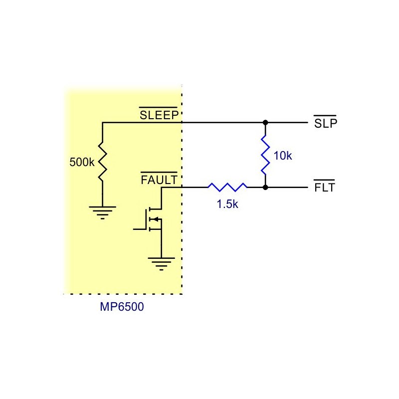
The FAULT output turns off when the F and H bridges are disabled due to current protection, overvoltage protection, thermal shutdown, or voltage dropout protection. It connects to the SLEEP pin via a 10 kΩ resistor, which functions similarly to FAULT. When SLEEP has a high state, it is not necessary to connect FAULT.
Note! As a result of connecting SLEEP and FAULT and when a fault occurs, the voltage on the SLEEP pin can drop below 2.1 V if it is not amplified enough. It is recommended to use resistor min. 4.7 kΩ with this pin or connect SLEEP directly to VCC. |
Current Limitation
To achieve high speeds, the motor supply usually needs to be higher than it would be without current limiting. For example, a stepper motor may have a maximum current rating of 1 A with a coil resistance of 5 Ω, which would indicate a maximum motor supply of 5 V. Using this motor with 9 V would allow higher speeds, but the current must be limited to less than 1 A to prevent damage to the motor.
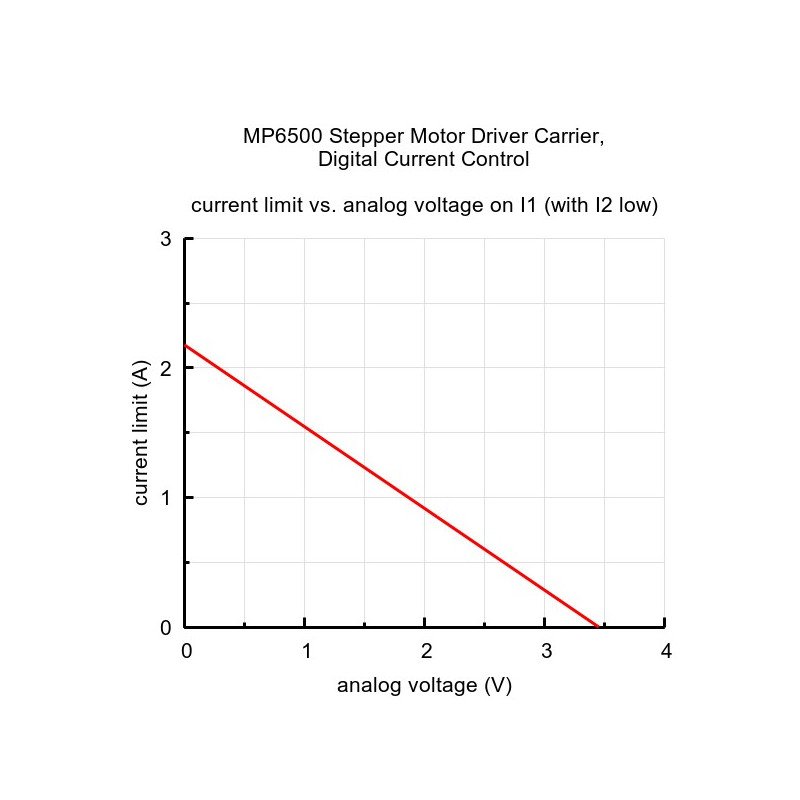
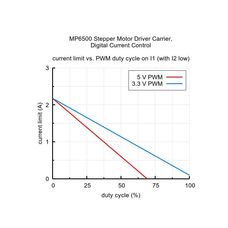
The controller uses the I1 and I2 outputs to set the current limit. If both I1 and I2 are disconnected, the current limit defaults to 0.5 A.
| I1 | I2 | Current limit |
|---|---|---|
| Z | Z | 0,5 A |
| low | Z | 1 A |
| Z | low | 1,5 A |
| low | low | 2 A |
Heat dissipation
The board is designed to dissipate heat at a current consumption of about 1,8 A per coil. If the current will be much higher, you should use an external heat sink for which you can use thermally conductive glue.
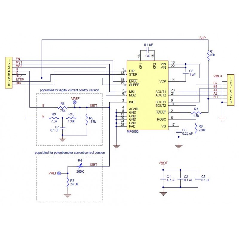
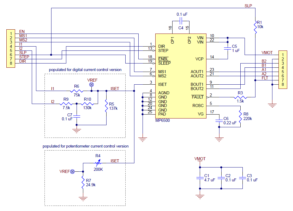
Circuit diagram
The circuit contains the necessary passive components for proper operation of the controller. Circuit diagram is shown in the figure below.
For supplying the logic part of the module a voltage in the range of 2.5 V to 5 V is required, which should be connected to the Sleeppin.The motor supply voltage from 4.5 V to 35 V is applied to the VMOTpin. The circuit can be used to control motors with a nominal voltage lower than the required 4.5 V. For this purpose, the maximum current consumption must be limited so as not to exceed the allowable motor current. For example, for a motor with a resistance of 5 Ω per coil and a current consumption of 1 A, the nominal supply voltage is 5 V. When supplied with 12 V, the current should be limited so that it does not exceed 1 A.
Useful links
| Name | Value |
|---|---|
| Voltage to | 4.5 V |
| Voltage from | 35.0 V |
| Current | 2 A |
| Channels | 1 |
| Width | 7.5 cm |
| Height | 1.2 cm |
| Depth | 9 cm |
| Weight | 0.004 kg |
 GLS
Shipping in 24 hours
from €8.07
 Raben - pallet delivery
Delivery in 3–5 days, no inside delivery
from €96.75
The full delivery terms are on the page Delivery and payment.
30 days to return, without giving a reason
If the product does not meet your expectations, you have 30 days from receiving the parcel to withdraw from the contract. The product only has to be complete. The right of return belongs to consumers (a purchase unrelated to business activity).
Complaints
If the product turns out to be faulty, you can make a claim under the guarantee or the statutory warranty. We handle claims without delay, at the latest within 14 working days of receiving the report together with the goods.
Be the first to ask a question about this product!
Instructions and documents
GPSR data
Product information
This product is a component intended for further assembly or prototyping. It is not a finished product within the meaning of the product safety regulations.
Products from the same category
See all