Product description: Polol 36v4 - High-Power 50V/6A stepper motor controller
Stepper motor controller based on DRV8711 systemallowsto control one bipolar stepper motor. The controller allows you to control the motor using a simple stepper and directional interface, but first you have to configure it via theSPI interface. This means that the control module must be capable of operating in SPI bus master mode (e.g.Arduino) and must be connected to the SDATi, SCLK and SCS pins. In addition, the controller has numerous protections such as protection against back voltage, too low voltage. The controller is equipped withPWM interfaceallowing to control twoDC motors.
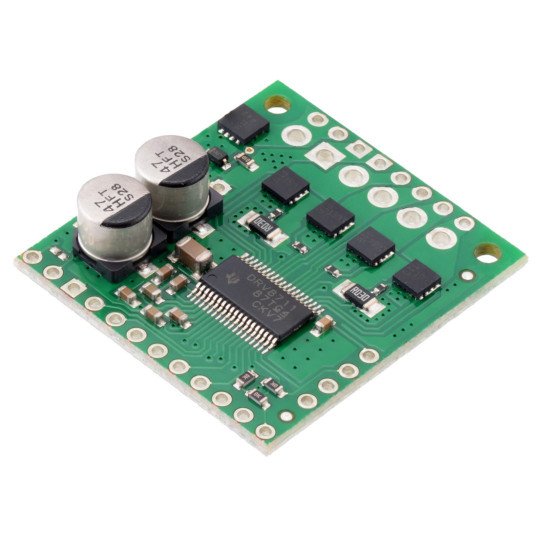
Complex stepper motor controller - Polol 36v4.
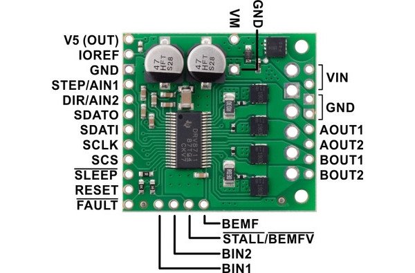
Outputs of Polol36v4module- High-Power 50V/6A stepper motor controller
| Pin | Description |
|---|---|
| VIN | Stepper motor power supply, 8 to 50 V (reverse polarity protection up to 40 V) |
| VM | Pin to access the stepper motor power supply. |
| GND | The weight of the system. |
|
AOUT1 AOUT2 |
Motor outputs: phase A coil ends. |
|
BOUT1 BOUT2 |
Motor outputs: phase B coil ends |
|
V5(OUT) |
Adjustable 5 V output. Provides access to voltage from the DRV8711 internal regulator. The controller can supply up to 10 mA. |
|
IOREF |
All signal outputs on the controller (except BEMF) are of the open collector type pulled up to the IOREF pin, so it should be supplied with voltage equal to the logical voltage of the control module (e.g. 3.3 V when the control module operates with logical voltage of 3.3 V). When the controller is used with a 5V operating module it can be connected to the adjacent 5V(OUT) pin. |
|
STEP/AIN1 |
One pulse given on the STEP pin causes one motor step, motor movement can also be controlled by the SPI interface so using this pin is optional. In PWM mode, it acts as AIN1 instead of STEP and directly controls the state of the AOUT1 output. |
|
DIR/AIN2 |
Input defining the direction of rotation of the stepper motor. The direction can also be controlled via the SPI interface, so the use of this pin is optional. InPWM mode, it acts as AIN1 instead of STEP and directly controls the state of the AOUT1 output. |
|
SDATO |
Pin, also known as MISO, is used to send data in the SPI interface. |
|
SDATI |
Pin, also known as MOSI, is used to receive data in the SPI interface. |
|
SCLK |
SPI clock line. |
|
SCS |
Addressing the SPI system. |
|
SLEEP |
By default, the pin is in a low state, which puts the motor controller into sleep mode where the motor controller is switched off and all analog circuits are in low power mode, while the digital circuits are still active, allowing access to the controller via the serial port. In order to start the device, a high state must be given to the pin. |
|
RESET |
System reset, activated by high state. This function does not work when the unit is in sleep mode. |
|
FAULT |
Pin is high by default. It switches to a low state if an error occurs. |
|
BIN1 |
In PWM mode, it directly controls the status of the BOUT1 output. |
|
BIN2 |
In PWM mode, it directly controls the status of the BOUT2 output. |
|
STALL/BEMFV |
Output type open collector, directly pulled up to the IOREF pin. The output goes to a low state when a motor stop is detected. |
|
BEMF |
EMF analogue output. The output signal on this pin can be used to implement more advanced algorithms and to detect engine stop. |
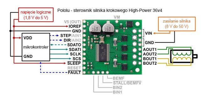
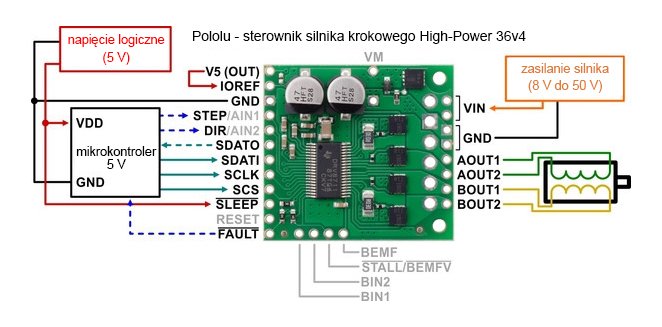
Connection diagram of Polol 36v4 - High-Power 50V/6A stepper motor controller
Although Pololu 36v4 allows you to control the motor via a simple stepper and directional interface, itmust first be configured via SPI buses, this means that the control module must be able to operate in master mode of the SPI interface and connect to the SDATi, SCLKand SCSpins. SDATO and FAULT pins are not required when using the controller.
Example of connection diagram of Polol 36v4 controller with microcontroller.
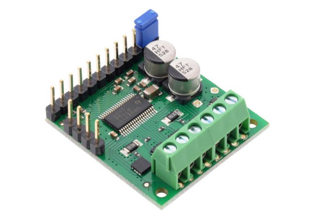
The Polol 36v4 controller is equipped with an internal 5 V controller, which can be used to power the IOREF pin when the board is used with a microcontroller working with 5 V logical voltage. For this purpose, you can use the supplied jumper or solder the pads on the board.
There are soldering pads on the board allowing to connect 5V(OUT) and IOREF leads permanently.
|
Attention! Connecting and disconnecting the motor while the controller is on can damage the system. |
Arduino library - Polol 36v4 - High-Power 50V/6A stepper motor controller
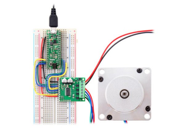
The manufacturer provides a ready-made libraryin GitHub service along withsample sketches for Arduino tiles,whichprovides basic functions for configuration and operation of the controller.
Connecting the controller withArduinocompatible module.
Polol 36v4 specification - High-Power 50V/6A stepper motor controller
- Motor supply voltage: 8 V to 50 V
- Current: max. per 4 A coil (with up to 6 A cooling)
- The supply voltage of the logical part: 1.8 V, 3.3 V and 5 V
- The interface:
- SPI
- Simple direction and step control interface
- PWM interface for DC motor control
- Working in 9 different modes:
- full step
- half step
- 1/4 step
- 1/8th step
- step 1/16
- 1/32 step
- 1/64th step
- 1/128 step
- 1/256 step
- Protection from:
- Back voltage
- undervoltage
- too high a current
- overheating
- Dimensions: 34 x 30 x 10 mm
- Weight: 9 g
Useful links |
