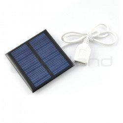
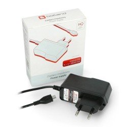
All mechanical and electronic systems require power. Without it, they cannot work. They need an energy source that drives them to operate. It is impossible to construct a machine that would work continuously without any energy source. With the development of technology, more and more sources of energy are emerging, which makes mobile devices that do not require a permanent power supply. These are accumulators and batteries, thanks to which we can use the device anytime and anywhere. They are perfect for mobile robots and mobile devices. Alternatively, there are power supplies, which in turn are plugged into an electrical outlet to provide power to the device, then it starts to work. A modern and at the same time inexhaustible source of energy is the sun. More and more often solar panels appear on the roofs of a building, whose task is to collect solar energy and convert it into electricity. Similar, but smaller panels are used in devices and machines, as well as to charge car batteries.
Power supply
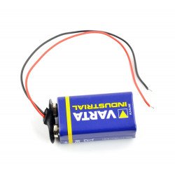
Clip for 9V battery with cable - 15cm
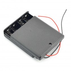
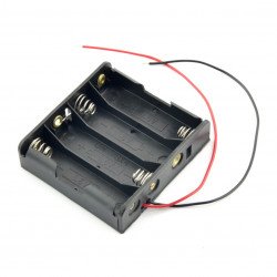
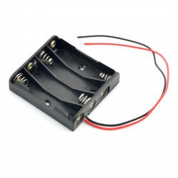
Connector for easy connection of popular 9 V (6F22) batteries with stripped cable ends.Battery holder for 4 AA (R6) batteries with cover and switch
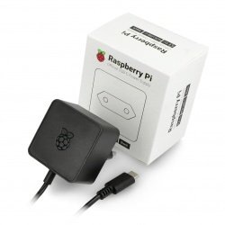
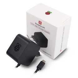
Basket with lid and switch for four AA batteries (big sticks).Power supply for Raspberry Pi 4 - USB C 5,1V / 3A - original black
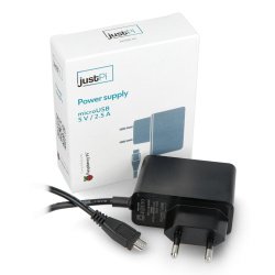
Original , black power supply for the minicomputer Raspberry Pi 4 with USB-C connector . The maximum current efficiency is 3 A.justPi power supply for Raspberry Pi 3B+/3B/2B/Zero - microUSB 5V/2,5A
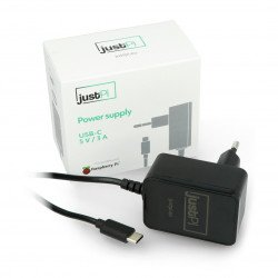
A power supply equipped with a microUSB connector compatible with the Raspberry Pi mini-computer. It has parameters allowing for optimal power supply to the Raspberry Pi 3B+ /...Power supply justPi C USB 5V/3A for Raspberry Pi 4B
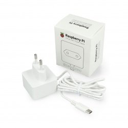
Dedicated power supply for the Raspberry Pi 4B minicomputer (1 GB, 2 GB and 4 GB RAM). It has parameters consistent with the recommendations of the Raspberry Pi foundation:...Power supply for Raspberry Pi 4 - USB C 5,1V / 3A - original white
Original , white power supply for the minicomputer Raspberry Pi 4 with USB-C connector . The maximum current efficiency is 3 A.Battery clip 9V (6F22) with cable
A connector to facilitate the connection of popular 9-volt (6F22) batteries with cables with insulation removed at the ends.Raspberry Pi 27W USB-C Power Supply - official 5,1V / 5A PSU for Raspberry Pi 5 - black
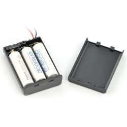
Official Raspberry Pi power supply with USB Type-C input and Power Delivery (PD) technology with a power of 27 W. It can provide a current with a maximum efficiency of 5...Battery holder - 3 x AA (R6) with cover and switch
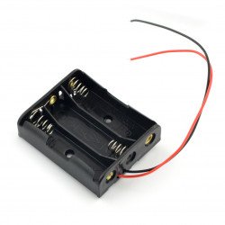
Basket with lid and switch for three AA batteries (big sticks).Power supply 5V / 2A - microUSB for Raspberry Pi Zero
Power supply dedicated to power the Raspberry Pi Zero minicomputer . Output voltage is 5 V and current capacity is max. 2 A. The power supply is equipped with a 1.2 m...- Reduced price
- SPECIAL OFFERS
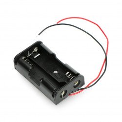
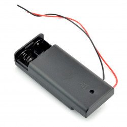
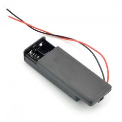
Battery holder for 2 AA (R6) batteries with cover and switch
Basket with cover and switch for two AA batteries (large fingers).Raspberry Pi 27W USB-C Power Supply - official 5,1V / 5A PSU for Raspberry Pi 5 - white
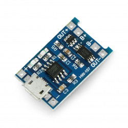
Official Raspberry Pi USB Type-C power supply with Power Delivery (PD) with a capacity of 27 W. The maximum current efficiency is 5 A at a voltage of 5 V , so it is able...Li-Ion charger TP4056 1S 3,7V microUSB with protection
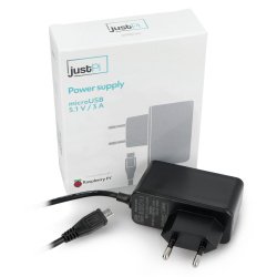
A simple charger for single-cell lithium-ion batteries with a nominal voltage of 3.7V. The system is powered via a microUSB connector or via cables. The module is protected...justPi power supply microUSB 5,1V / 3A for Raspberry Pi 3B+/3B/2B/Zero
Power supply with a 1.2 m cable terminated with a microUSB plug. The parameters of the power supply ensure optimal power supply to the Raspberry Pi mini-computer. The output...- Reduced price
- SPECIAL OFFERS
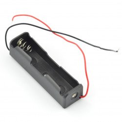
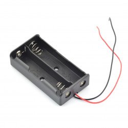
Cell holder for 2x 18650 - serial connection
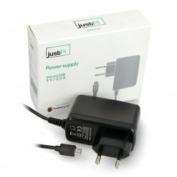
A basket for two 18650 type batteries. It has wires with insulation removed at their ends, which makes it easy to install the device.Power supply justPi for Raspberry Pi 3B+/3B/2B/Zero microUSB black 5V/2,5A
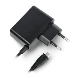
Dedicated power supply for Raspberry Pi 3B+/3B/2B/Zero series minicomputers with 5 V output voltage and 2.5 A current capacity. Equipped with a 1.2 m long microUSB cable.- Reduced price
- SPECIAL OFFERS
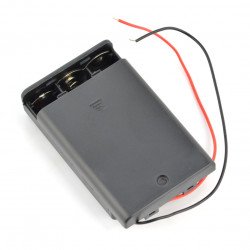
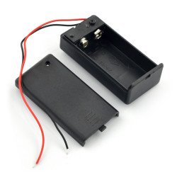
Battery holder for 1 pack 9V (6F22) with cover and switch
Basket with cover and switch for two 9V (6F22) type batteries.Power cable adapter IEC - Schuko (F) for UPS 20cm - black
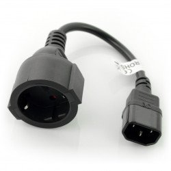
Adapter for the power cable with IEC 320 C14 on Schuko, with the length of 20 cm, it is mainly used for PC and server computers, and power supplies for laptops, UPS and any...Battery holder for 2 packs AAA (R6) with cover and switch
Basket with cover and switch for two AAA batteries (small fingers).Accumulators and batteries
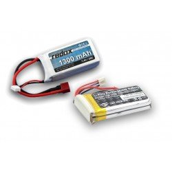
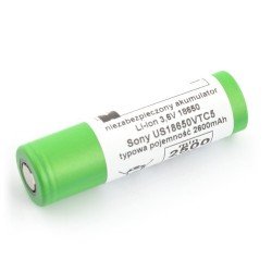
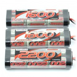
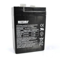
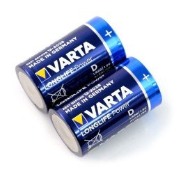
In the past, the electronics market was dominated by ordinary (disposable) batteries and nickel-metal hydride (NiMH) and nickel-cadmium (NiCd) batteries. The popularization of lithium-polymer (Li-Po) and lithium-ion (Li-Ion) batteries with small dimensions and weight and huge capacities, unattainable for other types of batteries, has caused a revolution - both in the category of mobile devices and RC models and robotics amateur. In this category you will find a wide range of batteries of all types mentioned, as well as various types of batteries in the most common dimensional standards. You will also find large gel batteries here.
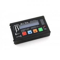
Chargers for all types of batteries
Once you have selected the battery, you must also equip yourself with a charger appropriate to its characteristics and size. Our offer includes both chargers for modeling packages and classic "finger" batteries in sizes R6 and R03. We also have special chargers dedicated to car batteries, including modern gel batteries, which have effectively replaced the old lead-acid designs from the market. In addition to ready-made devices, you will also find various types of charger modules that will allow you to easily build a charging function into your device (e.g. a robot), without having to worry about designing the necessary safeguards to protect the battery against overheating or even explosion. This category included probably the most popular types of chargers - micro USB and USB C, as well as wireless ones dedicated to mobile devices.
Power supplies from A to Z
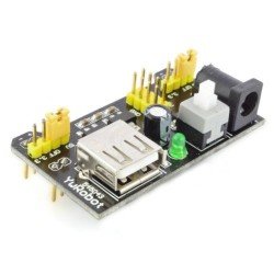
Our offer of power supply components and devices would not be complete if we did not provide all types of power supplies, used not only in connection with everyday devices, but also in electronics services and design studios. Here you will find a wide range of single- and multi-output laboratory power supplies, ATX computer power supplies, as well as uninterruptible power supplies (UPS) used to protect computer equipment or measuring equipment. We also have a wide range of power supplies for wall sockets (plugs), as well as industrial and automotive power supplies.
Power - FAQ
When selecting a power supply for any device, check what power parameters it requires. First of all, you need to take into account the type of power supply (AC or DC), current efficiency (amperage) and voltage, as well as select a power cable with appropriate capacity and with the right connector .


