- Reduced price
- SPECIAL OFFERS
Description
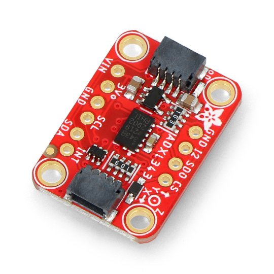
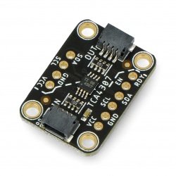
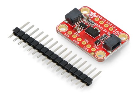
Sensor for measuring acceleration in three axes in the range of+-2g/4g/8g/16g. The module is supplied with the voltage from 2 V to 3.6 V, the voltage regulator is communicating through the I2C or SPI bus. The sensor is additionally equipped with two STEMMA QT connectors.
Module ADXL343 is the sequel to the popular ADXL345. It has 3-axis accelerometer with digital I2C and SPI interface. It is characterized bya wide sensitivity range and high resolution, it is working with10- or 13-bit internal ADC converter. The module has necessary for the correct operation of the system, passive elements. Pins are the popular goldpin connectors for connecting the sensor viawiresor to directly attach to the breadboard.
|
The product is compatible with Arduino Library and connection diagram with Arduino can be found atthis address. |
Communication of the ADXL343 QT module
The system can be connected with central unit via the I2C or SPI bus. To select I2C, you should indicate a logical one for CS pin or permanently pull CS to the voltage. The I2C address depends on the status at the pin SDO. In the case ofhigh status, it has a value: 0x1D, with the low status: 0x53. Details in the documentation andtutorial.
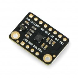
Pins of the ADXL343 QT accelerometer
The sensor has ten pins for mounting the goldpin connectors - pitch of 2.54 mm (included). STEMMA QT connectors compatible with SparkFun qwiic for the I2C bus can also be used to connect the sensor with the main module.
| Name |
Description |
| VIN | The input to the voltage regulator of 3.3 V, it allows the use of the sensor in systems of 5 V. |
| 3V0 | Regulator output of 3.3 V (<100mA). |
| GND | The ground of the system. |
| SCL | The data line of the I2C bus (TWI) / clock line of the SPI bus |
| SDA | Clock line of the I2C bus (TWI) / Data line of the SPI bus |
| SDO/ALT ADDR | The address selection of the I2C bus / Data line of the SPI bus |
| CS | Pin for the SPI bus - Chip Select. The logical one starts the I2C bus. |
| INT1 | The output of the external interrupt number 1 (details in documentation) |
| INT2 | The output of the external interrupt number 2 (details in documentation) |
Technical specification of the Adafruit ADXL343 QT module
| Parameter | Range |
|---|---|
| Supply voltage | 2.0 - 3.6 V |
| Voltage of the pins | 3.3 V (<100 mA) |
| Current consumption |
approx. 23 µA
|
| Three axes |
X, Y, Z |
| Communication interface | I2C (TWI) or SPI |
| The data transfer speed is determined by the user | (0.1 .. 3200 Hz) |
| Resolution |
|
| Measurement range | ±16 g |
| Operating temperature | from-40 °C to +85 °C |
| Board size | 25.5 mm x 17.8 mm x 2.9 mm |
| Weight | 1.7 g |
| Included | goldpin strap |
Useful links |
