Description
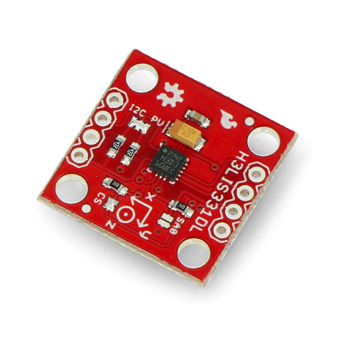
The MEMS module allows you to measure acceleration in three axes of the three-dimensional space. The device communicates via SPI or I2C.

To communicate with the central unit, the user can choose the SPI or I2C interface. The pins are holes for soldering the goldpin connectors (not included) which provide the connection of the sensor via wires or via direct attachment to the breadboard.
Specification
- Operating voltage: 2.16 V to 3.6 V
- A low energy consumption mode at the level of 10 μA
- I / O compatible with low voltage: 1.8 V
- 3 axis: X,Y,Z
- Adjustable range: ± 100 g ± 200 g / ± 400 g
- 16-bit output of data
- Sleep mode
- Pins: holes for goldpin connectors - 2.54 mm pitch
- 4 mounting holes with the diameter: 3mm
- Resistance to pressure of up to 10,000 g
Details concerning the technical parameters can be found in the documentation.
Pins
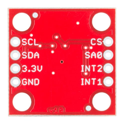
The sensor has pins for mounting goldpin connectors - 2.54 mm pitch (not included, purchased separately and self-soldered).

| Pin |
Description |
|---|---|
| 3.3 V |
The output voltage of 3.3 V in I2C communication |
| GND | The ground of the system. |
|
INT1 INT2 |
Outputs of the interrupts. |
| CS |
Chip select in SPI communication. |
| SA0 |
The output of the MISO data in the SPI communication. |
| SCL | Clock input in I2C and SPI communication. |
| SDA / SDI | The data line in I2C communication and MOSI for SPI. |
|
Useful links |


