Product description: Pololu DRV8825 - stepper motor driver 45V / 2.2A
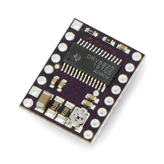
The module is based on the DRV8825 driver from the Texas Instruments company, it allows you to control a stepper motor with maximum current consumption of up to 1.5 A per coil (ifyou use cooling up to 2.2 A). It is supplied with the voltage in the range from 8.2 Volts to 45 VOLTS. It is recommended to see thedocumentationof the driver DRV8825 before the use.
Key features of the product
- The module has a simple interface to controlstep and direction
- It has the capability of operating in six modes: full-step, half-step, 1/4-step, 1/8-step, 1/16-step, and 1/32-step
- Provides control of maximum motor current via potentiometer what allows the use of higher than rated voltage for motors, this results in higher speed of steps
- The engines can be powered with voltage from 8.2 V to 45 V
- Current consumption up to 2.2 A ( 1.5 A without external cooling)
- Thanks to the built-in voltage regulator, the user doe not have to have an additional power supply for logical part.
- DRV8824 works with systems with a voltage of logical part of 3.3 V and 5V.
- It is protected against too high current and temperature, and short circuit, also has system blocking the start when the voltage is too low
- To increase the surface returning the heat, the board has been made in four-layered technology with a thickened layer of copper
- The open field of the mass from the bottom, allowing you to solder the cooling elements
- The module is compatible, when it comes to dimensions and ileads, with the system based onA4988 driver
In our offer s also a DRV8824version for engines with less power.DRV8824allows for the consumption of current to 0.75 A per coil (up to 1.2 A with additional cooling)
|
The set includes all the essential elements for driver connection - module and connectors for self-soldering |
Connection of driver
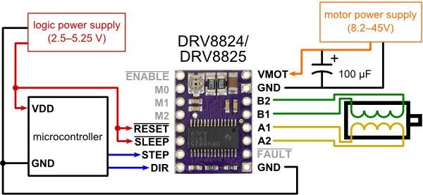
To control a bipolar stepper motor,it is necessary to connect the system in accordance with the following figure. The driver allows to work with some unipolar engines, the details are inthe instructions.
Management of DRV8825 driver
One pulse indicated on the pin STEP, causes one step of the motor in the selected directionby making the appropriate logic state (high or low) to the DIRoutput. Pins STEP and DIR are not internally pulled up. If the motor should only rotate in one direction, the DIR pin canpermanently be connected to VCC or GND.
The system has three inputs for power consumption's control: RESET SLP and EN, their description is indocumentation. Please note that these leads are not connected to anything. If not used, they should be externally pulled up to the supply voltage (specify the high status - logical one from the range of 2.2 V to 5.5 V)).
Driver DRV8825 also has a lead labeled as FAULT. The low status(logical zero) indicates the emergence of disorders in the system, for example, the activation of one of the protections. On the board, lead is connected with the SLEEP pin, and thus, indicating a high position to SLEEP pin, also pulls up the FAULTto VCC. Through the application of the serial protective resistor, the FAULT lead can also be connected to the VCCvoltage, which makes the module pin-compatible with the versionA4988.
Power
The chip can be powered with voltage from a range of 8.2 Volts to 45 V connected between the pins VMOT (+) and GND (-). The voltage must be filtered through the external capacitor placed as close as possible to the board driver. Its capacity depends on the maximum current consumed by the motor.
|
Attention! In certain conditions, even a relatively low supply voltage may result in voltage peaks with a high amplitude, exceeding the allowed value of 45 V. This situation causes irreversible damage to the system. One way to avoid this problem is the placement of the capacitor (at least 47uF), as close as possible to VMOT and GND pins of the controller.
The connection and disconnection of the engine while the driver is turned on can damage the system. |
Driver resolution
Micro-step driver like DRV8825 allows engine operation with high resolution up to 1/32 of step. The step size is selected via inputs MODE1, MODE1 and MODE2 - available modes are presented in the table below. By default, all three pins are pulled down to ground via resistor 100kΩ. Leaving them not connected means that the choice of full stepmode. For example, when using a motor with a resolution of 200 steps per revolution, choosing a ¼ of steps mode, means working with a resolution of 800 positions per revolution.
| MODE0 | MODE1 | MODE2 | Resolution |
|---|---|---|---|
| Low | Low | Low | Full step |
| High | Low | Low | 1/2 of step |
| Low | High | Low | 1/4 of step |
| High | High | Low | 1/8 of step |
| Low | Low | High | 1/16 of step |
| High | Low | High | 1/32 of step |
| Low | High | High | 1/32 of step |
| High | High | High | 1/32 of step |
Current limit
To maintain high switching speed of steps, you can use a higher motor supply voltage than rated. You should only limit the maximum current flowing through the coils to the catalogue value of engine.
The module allows the active current limit via the potentiometer. One of the ways to introduce the limit, is to set the driver to full step mode and measuring the current flowing through one coil without indicating the signal on the STEPinput. The measured current is 70% of the set limit (both coils are always on and limited to 70% in the full step mode).
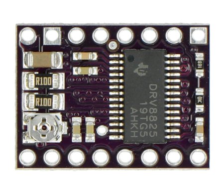
Another way is to measure the voltage on the REF lead (marked with a circle on the PCB), as well as the calculation of the actual limit (measuring resistors have a value of 0.1Ω). The current limit can be calculated from the formula:
Current Limit = VREF × 2
For example, if the engine can consume up to 1A, then the refere voltage on the VREF pin, should be 0.5 V.
Dissipation of heat
The board was designed so that it could dissipate the heat at a constant current consumption of about 1.5 A to the coil. If the current is significantly higher, you should use an externalradiator which can be installed usingthermo-conductive glue.
Scheme
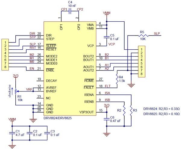
The system includes the necessary passive components for the correct operationof the driver. The scheme of connections is shown in the figure below.
The main differences from version A4888
DRV8825 module was designed to be compatible with the version based onA4988. The boards have the same shape, size and location of the leads. However, there are several differences between them:
- Pin used as supply voltage of the logic part A4988, has been replaced with the FAULT pin because the DRV8825 does not require additional power. FAULT was connected through a protective resistor, and hence it may be successfully used in the systems designed for the A4988 module, and on this pin will be indicated supply voltage of the logic part (2,2 V to 5,5 V).
- In module DRV8825, SLEEP pin, by default, is not pulled up to a power source, it was connected with a FAULT lead through a 10K resistor. In systems designed for the A4988 chip, using a supply voltage of a logic part connected to the FAULT, the 10K resistor pulls the SLEEP to the supply voltage, setting the high state.
- The potentiometer which limits the maximum current for motors is in a different place
- The DRV8825 allows you to work in 1/32 of step mode, while the A4988 worked up to 1/16-step
- The DRV8825 has a wider supply voltage up to 45 V (A4988 to 35 V) which also makes it less vulnerable to short, electric pulses of high amplitude (so-called voltage peaks)
- Leads have different names but perform the same function
Pololu DRV8825 specification
- The supply voltage: 8.2 V - 45 V
- DC per coil: 1.5 A
- Maximum short-term current per coil: 2.2 A
- Supply voltage of the logic part: 2.5 V - 5.25 V
- Resolution: 1, 1/2, 1/4, 1/8, 1/16, and 1/32 of step
Useful links |


