


 IC Test Board")
 IC Test Board")
 IC Test Board")
 IC Test Board")
 IC Test Board")
 IC Test Board")
 IC Test Board")
 IC Test Board")
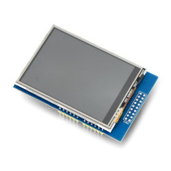
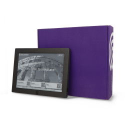
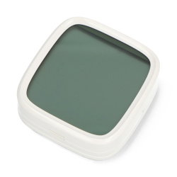
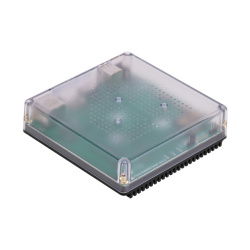
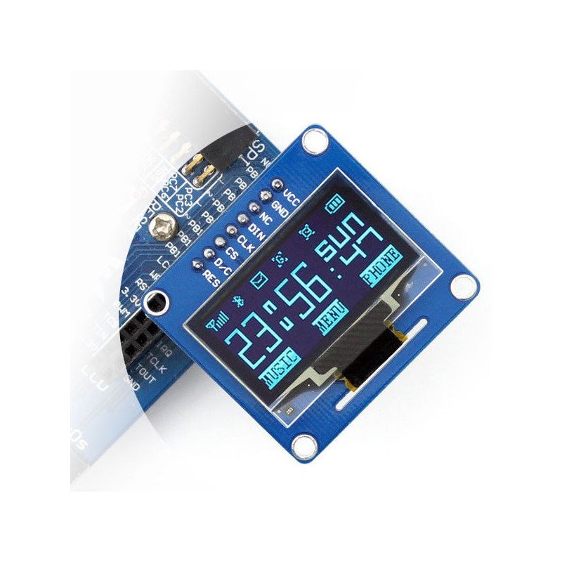
OLED blue display with a diagonal of 1.3" and a resolution of 128 x 64 px. The screen is based on SH1106 driver, works with voltages of 3.3 V and 5 V, communication via SPI or I2C. It has soldered straight goldpin connectors.
OLED blue display with a diagonal of 1.3" and a resolution of 128 x 64 px. The screen is based on SH1106 driver, works with voltages of 3.3 V and 5 V, communication via SPI or I2C.
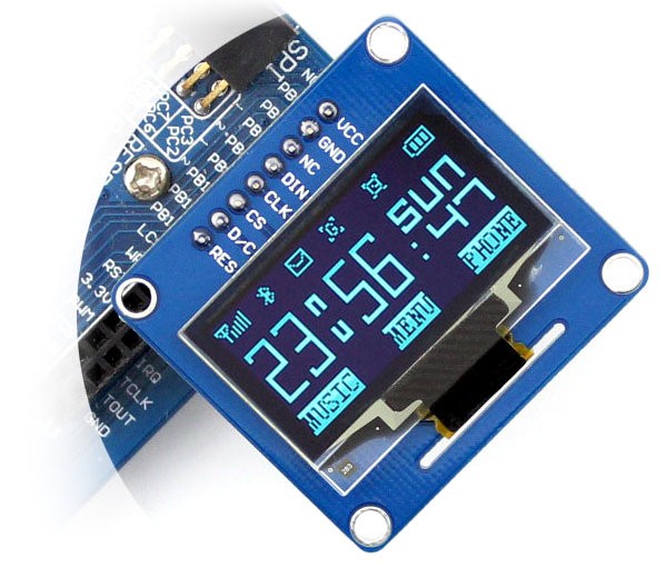 This version has soldered straight goldpin connectors. In our offer you will also findthe display with angled connectors.
|
The manufacturer provides auser manualandlibrary to support the screen. |
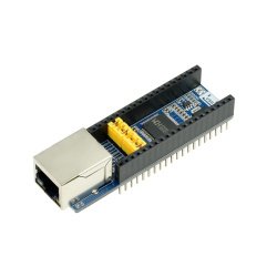
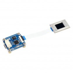
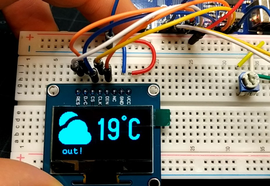
The module has soldered angled goldpin connectors - raster 2.54 mm, communicates via SPI or I2C. Description of the specific pins is shown in the table.
| Pin | Symbol | Description |
|---|---|---|
| 1 | VCC | Supply voltage from 3.3 V to 5.0 V. |
| 2 | GND | The ground of the system. |
| 3 | NC | Should be left unconnected. |
| 4 | DIN | Data line of SPI interface. |
| 5 | CLK | Clock line of the SPI interface. |
| 6 | CS | Select the device SPI bus is activated by low state. |
| 7 | D/C |
Select operating mode - low means the transmission of commands, high means transmission of data. |
| 8 | RES | Reset system is activated by the low state. |
The bus selection is carried out with jumpers BS0 and BS1, which are on the back of the board. By default the display is in 4-wire SPI mode. For details, see the table below.
|
Mode work |
Pin BS0 |
Pin BS1 |
Function DIN |
Function
CCS |
|---|---|---|---|---|
| 3-wire SPI | 1 | 0 | MOSI | SCLK |
| 4-wire SPI | 0 | 0 | ||
| I2C | 0 | 1 | SDA | SC |
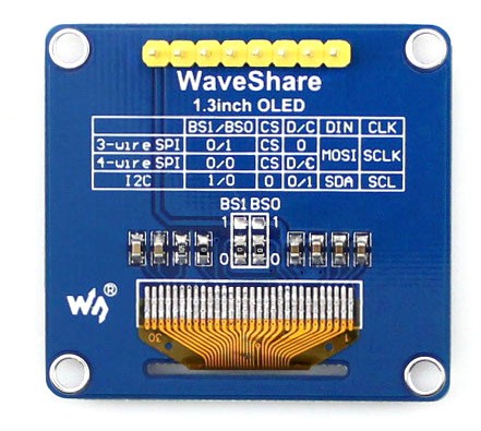 Jumper for selection of operation mode is located in the centre of the module: BS1 and BS0.
|
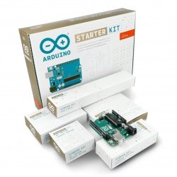
The product is compatible with Arduino |
Useful links |
| Screen - type | OLED |
| Screen - diagonal | 1.3'' |
| Screen - interface | SPI+I2C |
| Screen - touch | no |
| Screen - resolution | 128x64px |
| Test | 4 |
| Niebezpieczne | Component |
| Package width | 8 cm |
| Package height | 1.8 cm |
| Package depth | 8 cm |
| Package weight | 0.009 kg |
| Fabian
02/05/24 | Question: How do I change the interface from SPI to I2C? |
Answer: You must move BS1 from 0 to 1, according to the instructions on the board. | |
 128x64px SPI/I2C - straight connectors - Waveshare 10451")

Product Information
The product is a component intended for further assembly/prototyping. It does not constitute a standalone finished product within the meaning of product safety regulations.
Dane GPSR
Country of Origin: China
Manufacturer Contact Details: Seednew Limited 3/F, Building 6, Shanglilang Zhichuangyuan, Pingji Avenue, Nanwan Street, Longgang District, Shenzhen, 518115, China
EU Marketer Contact Details: BOTLAND B. DERKACZ SP. K. Gola 25A - 63-640 Bralin
 IC Test Board")
 IC Test Board")
 IC Test Board")
 IC Test Board")
 IC Test Board")
 IC Test Board")