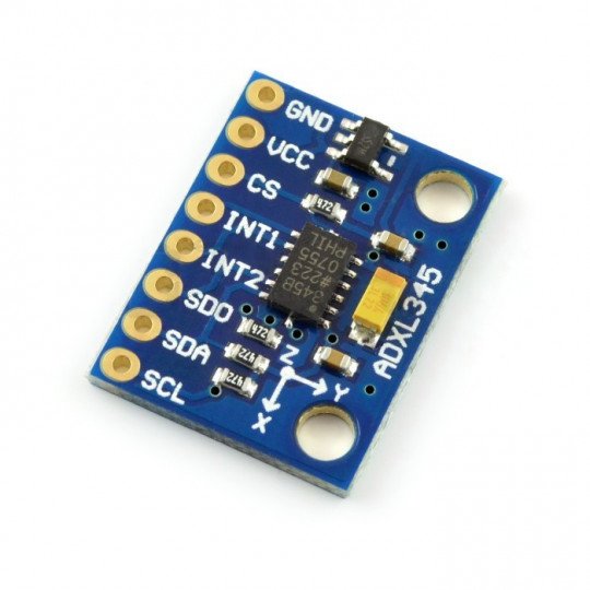
 Specification
- Supply voltage: 3 V - 5 V
- The voltage of pins: 1,6 V to 3,6 V
- Current consumption: about 25µA
- standby mode: 0,1µA
- Three axes: X, Y, Z
- Communication interface: I2C (TWI) or SPI
- Resolution: 10 to 13 bit for each axis
- Measurement range: ±16 g
- Operating temperature:-40 °C to +80 °C
- The dimensions of the board: 20 x 16 x 5 mm
- The set also includes goldpin strip
Description
Sensor for measuring the acceleration in three axes in the range of +/- 16 g. The module is powered with the voltage from 3 to 5 V, it has the voltage regulator, communicates via the I2C bus (TWI) or SPI.
The module has necessary for the correct operation of the system, passive elements. Pins are popular goldpin connectors for connecting the sensor viawiresor to directly attach the breadboard.
|
The product is compatible with Arduino Library and connection diagram with Arduino, you can find it atthis address. |
Communication
The system can be combined with the central unit via the bus I2C or SPI. To select I2C, you should indicate logical unit to CS pin or to pernamently pull CS at a constant voltage. The I2C address depends on the state at pin SDO. In the case ofhigh status, it has a value of: 0x1D, at low status: 0x53. Details, in documentation andtutorial.
Pins
The sensor has eight pins for the installation of connectors of goldpin type - pitch of 2.54 mm (included).
| Name |
Description |
| GND | The ground of the system |
| VCC | The module's supply voltage is in the range from 3 V to 5 V |
| CS | Pin for the SPI bus - Chip Select. The logical one starts the I2C bus. |
| INT1 | The output of the external interrupt number 1 (details in documentation) |
| INT2 | Output of the external interrupt No. 2 (details in documentation) |
| SDO | The address selection of I2C bus/data line of SPI bus |
| SCL / SCLK | The data line of the I2C bus (TWI) / clock line of the SPI bus |
| SDA / SDI | Clock line of I2C bus (TWI) / data line of SPI bus |
Useful links |


