Description
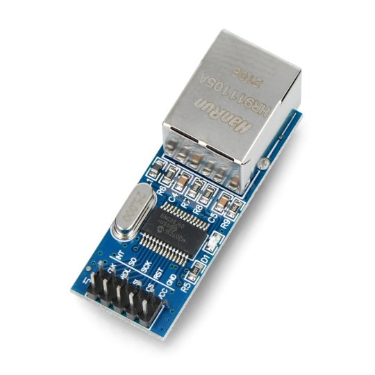
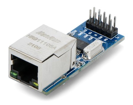
A module that enables the connection of the microcontrollers and development kits, including the Arduino, with the Ethernet network. The communication interface is the popular, digital SPI bus. On the board is Ethernet RJ-45 slot for the network cable and goldpin pins for connection to the main board. The supply voltage of the system is 3.3 V and the dimensions of the whole are: 51 x 19 x 16mm.
|
Available is alibrary for the Arduinomodule, along witha user manual for connection. |
Specification
- Supply voltage: 3.3 V
- Maximum transfer rate: 25 MHz
- Communication interface: SPI
- The MAC address should be set in the program
- Module type: 10Base-T
- Operating temperature: -40 °C to 85 °C
- Dimensions: 51 x 19 x 16 mm
Details inthe documentationof the chip ENC28J60.
Pins
The module has goldpin pins for connecting with anydevelopment kit or dedicated PCB using the availablewires. The arrangement of pins is shown in the figure below.
Table describes the description of pins of the Ethernet ENC28J60 mini module
|
Name |
Description |
|
VCC |
Supply voltage is 3.3 V. |
|
GND |
The potential ground of the system. |
|
RESET |
The reset of the system is activated with the low status. By default, it is in the high status - internally pulled up to VCC (pull-up). The pin tolerates the voltage of 5V. |
|
CS |
Chip select - selects a device of the SPI bus. It is activated with the low status. By default it is in the high status - internally pulled up to VCC (pull-up). The pin tolerates the voltage of 5V. |
|
SCK |
The clock input of the SPI bus. Pin tolerates the voltage of 5V. |
|
SI |
Line of the input data of the SPI bus. Pin tolerates the voltage of 5V. |
|
SO |
Line of the output data of the SPI bus. Pin tolerates the voltage of 5V. |
|
CLKOUT |
Programmable output clock line. |
|
WOL |
Must be left not connected |
|
INT |
Internal interrupt output . |
Useful links |


