Description
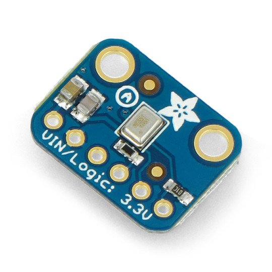
The module is equipped with a digital microphone with a range from 50 Hz to 15 kHz, and also with the I2S bus. Work voltage in the range of 1.6 V to 3.6 V.
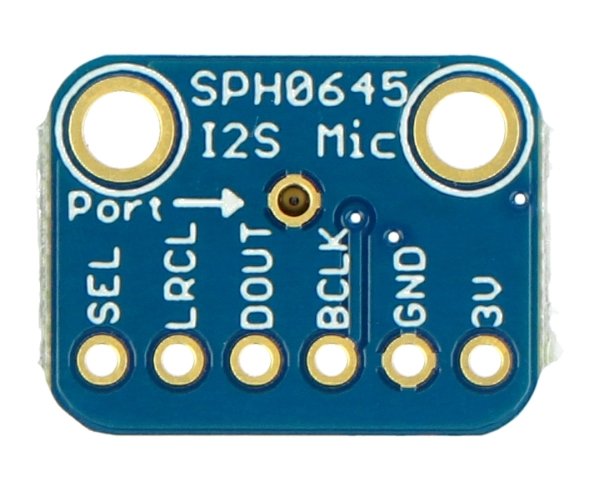
The microphone input is located at the bottom of the board, therefore you should be mindful of the corresponding turning plate in the direction of the sound. The device works with the I2S bus and only works with devices on this bus, for example,Arduino M0,M0 FeatherorRaspberry Pi.
Connection
The module has a simple goldpin connectors for self-soldering - raster 2.54 mm, communicates via I2S. Description of the specific outputs is given in the table.
| Pin | Symbol | Description |
|---|---|---|
| 1 | 3B | Power to the layout from 1.6 V to 3.6 V. |
| 2 | GND |
The ground of the system. |
| 3 | BCLK |
Bit Clock. The input coming from microcontroller informing the microphone in data transfer mode. |
| 4 | DOUT | Data output from the microphone. |
| 5 | LRCL |
Left/Right Clock. Tells you when to start the transfer. Low sends on left channel and high state on right. |
| 6 | SEL |
The selection of channel. Default in the low state that is, the broadcasting is on the left channel. When you connect to a high state it is transmitted through the right channel. |
Specification
- Working voltage: 1.6 V to 3.6 V
- Operating range: 50 Hz to 15 kHz
- Digital microphone
- Communication: I2S
- Complete goldpiny for self-soldering
- Dimensions: 17 x 13 x 2 mm
Useful links |


