

Over 500,000 customers already trust us. With us you get:
same-day shipping for products marked “24h shipping”
our own service centre in Poland
30 days to return and free delivery in Poland from PLN 500
4.9/5 on TrustMate and 4.9/5 on Google (almost 4,000 reviews)
VAT invoice, leasing and instalments for businesses
For businesses
individual quote for larger quantities
VAT invoice
For schools and universities
orders based on requests for quotation
help with choosing kits for your lab

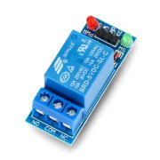
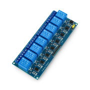
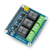
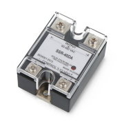
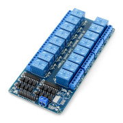
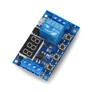
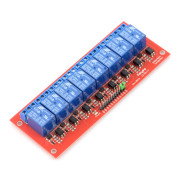
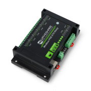
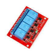
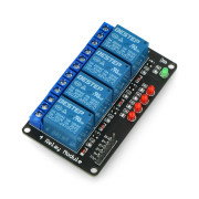
Relay module 1 channel with optoisolation - 10A/250VAC contacts 5V coil
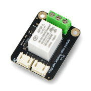
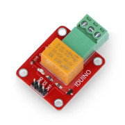
The module is equipped with relay SRD-05 with coil powered with a voltage of 5 V with optical isolation of input and mounting holes. The system allows you to control actuators with microcontroller ports or with any commissioning set.
We could not load the price.
The promotional price does not combine with quantity discounts.
Specification
- The supply voltage VCC: 5 V
- Activated with low state
- Relay JQC-3FF-S-Z (documentation)
- Parameters of contacts for resistive load:
- 125 VAC / 10 A
- 250 VAC / 10 A
- 30 VDC / 10 A
- 28 VDC / 10 A
- Optoisolation EL817 (documentation)
- The dimensions of the board 53 x 28 mm
- Diameter of mounting holes: 3 mm
* Maximum contact voltage depends on the type of load - details inthe documentationtab. Contact Data.
Description
The module allows to control the actuators consuming the current up to 10 A using the microcontroller's ports or any commissioning set (includingArduino,Rasbperry PiandSTM32Discovery). Optoisolation seperates the control signal from the part associated with the power of relay, thereby providing work safety of the management system.
For proper operation, it is sufficient to mount the power supply of relay and digital control signal. Leads are the standardgoldpin strips with pitch of 2.54 mm which enables connecting via popular connecting cables.
Examples of application
- Driver of lighting
- The driver of actuators
- Switch for electric devices, including motors
Connection
The module has three input leadsVCC, GND, IN. For the system to work correctly, you must connect the power supply 5 V to the VCC pin, ground GND and the input signal IN.
Output leads are describe as NO - disabled by default, NC - connected, by default,with COM. Indicating the low status on the IN pin, switches the relay and makes the connection between the COM and NO, disconnecting the COM from NC.
Useful links
- <a href="/index.php?controller=attachment&id_attachment=244" target="_blank" rel="noopener noreferrer">D</a>ocumentation of<a href="/index.php?controller=attachment&id_attachment=1397" target="_blank" rel="noopener noreferrer"> relay JQC-3FF-S-Z</a><a href="/index.php?controller=attachment&id_attachment=244" target="_blank" rel="noopener noreferrer"></a>
- <a href="/index.php?controller=attachment&id_attachment=245" target="_blank" rel="noopener noreferrer">Documentation of optoisolator </a><a href="/index.php?controller=attachment&id_attachment=245" target="_blank" rel="noopener noreferrer">EL817</a>(.pdf)
- Example of connecting a relay to the Raspberry Pi
| Name | Value |
|---|---|
| Channels | 1 |
| Interface | Digital I / O |
| Width | 10.5 cm |
| Height | 4 cm |
| Depth | 2 cm |
| Weight | 0.016 kg |
 GLS
Shipping in 24 hours
from €8.07
The full delivery terms are on the page Delivery and payment.
30 days to return, without giving a reason
If the product does not meet your expectations, you have 30 days from receiving the parcel to withdraw from the contract. The product only has to be complete. The right of return belongs to consumers (a purchase unrelated to business activity).
Complaints
If the product turns out to be faulty, you can make a claim under the guarantee or the statutory warranty. We handle claims without delay, at the latest within 14 working days of receiving the report together with the goods.
Question: 1) Is it enough to connect this relay directly to the Arduino? Or add some resistor along the way? 2) Is the current of the Arduino port (supposedly 40mA) enough to control the relay?
Question: This component is finally what voltage? VCC 24V or 28V? 5V signal?
The coil is powered by 5 V.
Instructions and documents
GPSR data
Product information
This product is a component intended for further assembly or prototyping. It is not a finished product within the meaning of the product safety regulations.
Products from the same category
See all