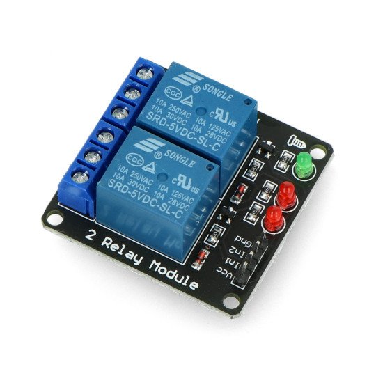
Product description: Relay module, 2 channels - contacts 10A/250VAC - coil of 5V
The module allows to control the actuators consuming the current up to 10 A using the microcontroller's ports or development set (includingArduinoorSTM32Discovery). In the system is a transistor amplifier which allows you to control the relay directly from the microcontroller's port (5 V). Activating the relay is signaled by truning on of the corresponding LED.
For proper operation, it is sufficient to connect the power supply of the relay and the digital control signal. Pins are the standard goldpin straps with the pitch of 2.54 mm which allows for the connection using the popular connecting cables.
Examples of application
- Driver of lighting
- The driver of actuators
- Switch for electric devices, including motors
Relays module, 2 channels - contacts of 7A/240VAC - coil of 5V
Connection
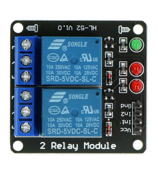
The module has four input pins VCC, GND, IN1, IN2. For the system to work correctly, you must connect the power supply of 5 V to the VCC pin, ground GND and the input signal INx.
Output pins are marked as NO - are disabled by default, NC - by default connected with COM. Specifying the high status at the INx pin, switches the relay's contacts and makes the connection between the COM and NO, disconnecting COM from NC.
Specifications of the relay dual channel module
- The VCC supply voltage: 5 V
- Activated by the low status
- Relay SRD-05VDC-SL-C (documentation)
- Coil voltage: 5 V
- The maximum voltage of the contacts: 250 V AC, 110 VDC*
- Maximum current: 10 A
- The transistor amplifier in the system
- 5 LEDs
- 4 - signaling the activation of the relay
- 1 - signaling the power connection
- Board sizes: 44 x 44 mm
- Diameter of mounting holes: 3 mm
* Maximum contact voltage depends on the type of load - details inthe documentation, tab. 7. Contact Rating.
Useful links |


