Description
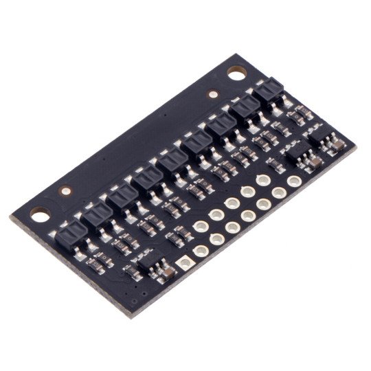
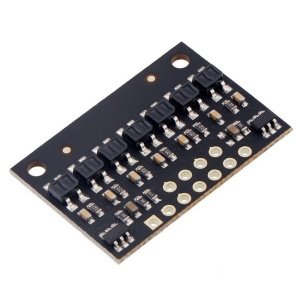
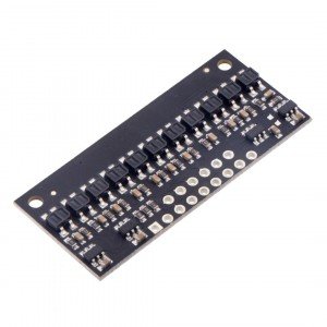
The strap is used in robots like line follower as sensors detecting the track as a black line on a white background. The module consists of nine reflective sensors that contain the transmitting IR LED and receiver in the form of phototransistor. Output are the digital signals that can be read using any microcontroller, including Arduino. Sensor QTR has no lenses and features with a higher consumption of current than QTRX.
Service
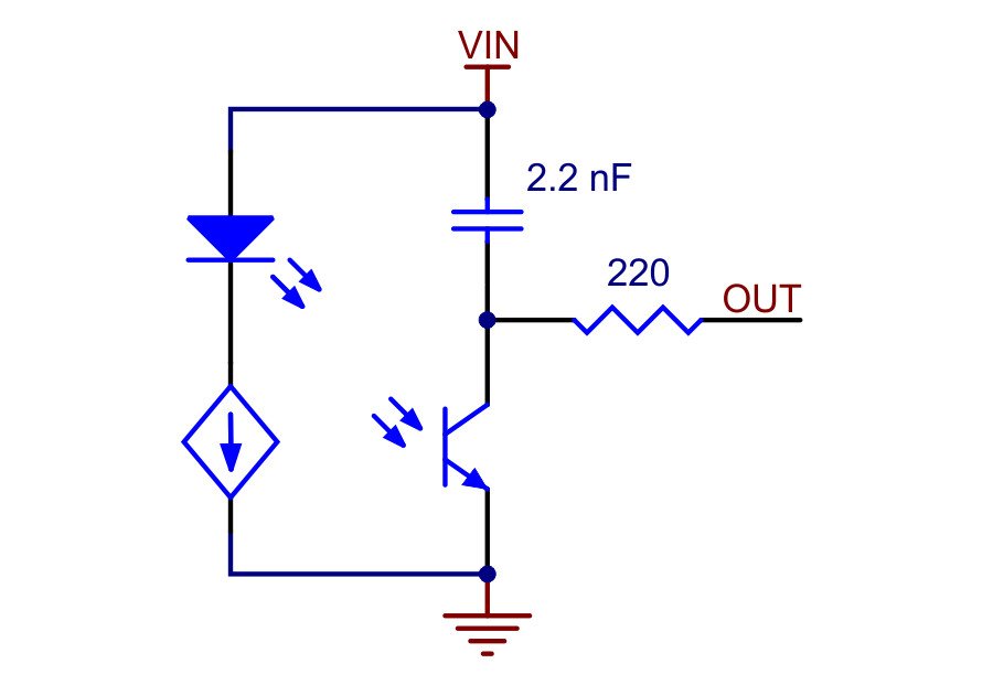
Strap QTR-HD-07RC has digital outputs. Reading the measurement data is carried out by charging the capacitor (indicating the high status), and measuring the time of its discharge through phototransistor. This option has the following advantages:
- It does not require an analog-to-digital converter
- It gives the opportunity for parallel reading of the value from the six sensors
A typical sequence of the reading of sensor values:
- Turning on IR LEDs (optional)
- Setting the I/O pins of the microcontroller as output and the creation of the high status
- Wait a few micro seconds - charging the 2.2 NF capacitor
- Setting the I/O pins as input (high impedance status)
- Measuring the discharge time of the capacitor by waiting until the I/O lines go to low status
- Disabling the IR LEDs (optional)
|
The product is compatible with Arduino For users of Arduino modules, manufacturer has prepared a special library that simplifies the maintenance of the sensors: library of Arduino. |
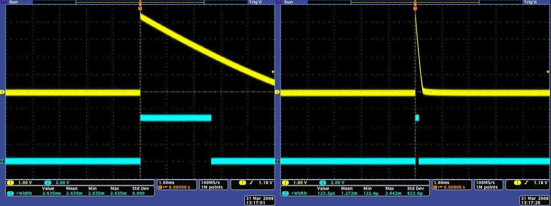
The optimal distance of the sensors from the surface, is 5 mm, the maximum, at which the sensor operates, is 40 mm. To picture the situation, we present the oscilograms showing the detection of black line on a white background at different distances from the surface.
Digital signal (yellow) after the detection of black lines on a white surface in the close distance and clock frequency of the microcontroller (blue) - from the left and then the right side.
Scheme
Each of phototransistors has an external pulling-up capacitor and the auxiliary circuit providing the read of data from the sensors by measuring the time of discharge.
Current of each LED was set to 30 mA, the maximum current consumption of the module is approximately 155 mA.
Diagram of the module QTR-HD-09RC.
Controlling the emitter
Matrixes have reflective sensors that can maintain a constant current through your IR transmitters, maintaining a constant brightness of the emitter, regardless of the supply voltage. Emitters can be controlled with the CTRL pins on the board, control is depending on the size and density of the matrix:
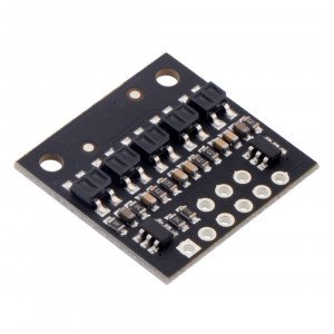
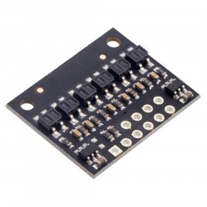
- Modules with five or more sensors of high density (HD) have two pins controlling the emitter: ODD CTRL and EVEN CTRL. By default, they are connected with resistor of 1 kΩ, by default, turning on all transmitters and allows for their control using a signal on each of the pins. Pins ODD CTRL and EVEN CTRL can be used separately for independent control of transmitters with odd numbers and even numbers.
- Modules with three or more sensors with medium density (MD) also have two pins controlling the emitter, only CTRL ODD pin will be able to manage in this version.
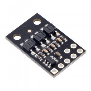
- Modules with four or less sensors have a single CTRL pin that controls all the super-emitters.
Specification:
- Number of sensors: 9
- Supply voltage: from 2.9 V to 5.5 V
- Current consumption: 155 mA
- Current consumption of one LED: 30 mA
- Outputs: digital
- The optimal measurement distance: 5 mm
- The maximum distance of measurements: 40 mm
- Light wavelength: 940 nm
- Sensor type: QTR
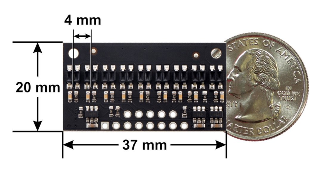
- Distance between sensors: 4 mm
- Dimensions 37 x 20 x 3 mm
- Weight: 2.1 g
Useful links |
