Product description: By-pass voltage regulator 1.5 ohm, 15 W - precise LV regulation - Pololu 3778
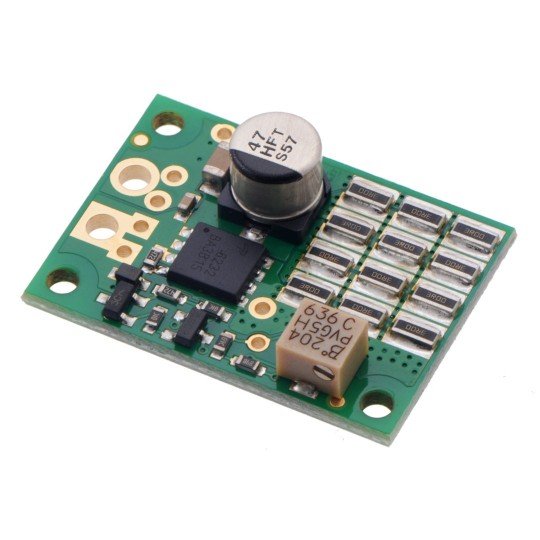
The shunt regulator canprotectpower suppliesfrom voltage spikes generated bymotor controllersconnected to them. This version hasprecise voltage regulationfrom 4 V to 18 V, ,4.1 Ωshunt resistance and32SMT shunt resistorslocated on one side of the PCB. An externalpotentiometercan be used toset the voltage.
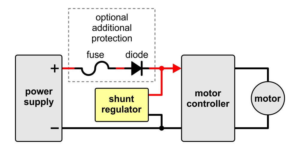
The regulator should be installed in parallel with thepower supplyfor proper operation. The supply voltage should be lower than the regulator voltage and the regulator should draw only resting current less than 0.5 mA. Any voltage pulses above the setting will cause the regulator to draw significantly more current, dissipating energy and limiting the range of voltage variation.
Wiring diagram of a shunt regulator between the power supply and the motor controller.
Wiring diagram of the regulator
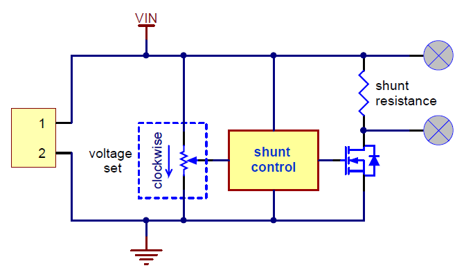
Below is a simplified schematic of a shunt regulator. The circuit monitors the voltage and controls theMOSFET, which allows current to flow through the shunt resistance, which sets the maximum current the device can absorb.
Simplified schematic of a shunt regulator.
All Pololu shunt regulators differ only in voltage value and resistance. The available versions can be found in the table below:
| Voltage | ||||||||
|---|---|---|---|---|---|---|---|---|
| 13,2 V | 26,4 V | 33,0 V | Fine adjustment LV | Fine adjustment of HV | ||||
| Power: | 3 W | |||||||
| 9 W | ||||||||
| 15 W | ||||||||
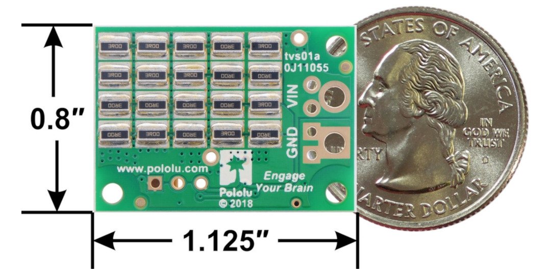
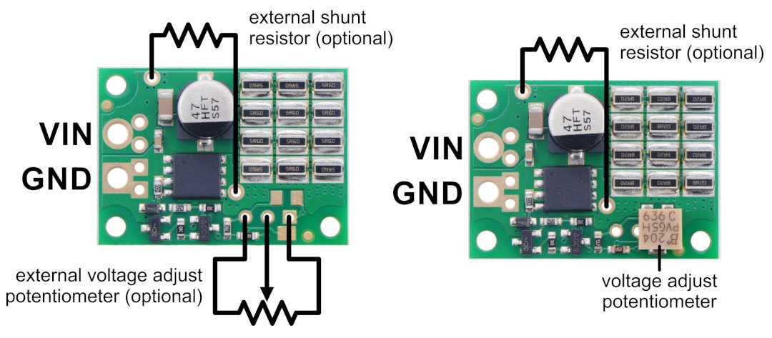
On the left is the bottom appearance of the 3 W and 9 W regulator, while on the right is the 13 V, 1.50Ω, 15 Wregulator.
Note!
The power is primarily intended to indicate the relative average power consumption for a maximum of a few seconds. The boards are designed to clip occasional, short pulses. Prolonged application of voltage above the set point will destroy the regulator almost immediately (in less than a second).
Adjusting the voltage set point
The shunt regulator is available in two adjustable versions with multi-turn potentiometers. All fixed voltage versions can also be adjusted by adding a potentiometer on the board.
The two adjustable versions differ only in the shunt resistance and the mapping optimization of the voltage setting potentiometer.
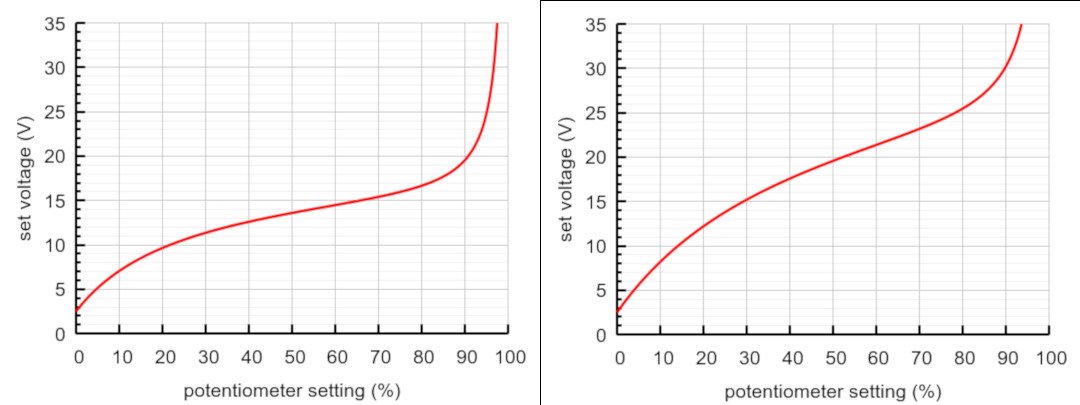
Schematics of the set voltage relative to the adjusted potentiometer:
LV curve on the left: 1.50Ω, 15 W; HV curve on the right: 4.10 Ω, 15 W.
Diagrams of the adjusted voltage against the adjusted potentiometer
The HV curve was obtained using a 200 kΩ potentiometer with a 33.0 V plate, using a 200 kΩ potentiometer with low voltage constant value plates will disturb the mapping by looking like an LV curve. (100 kΩ or lower value potentiometers can be used at the expense of higher resting current, since the full supply voltage is applied through this potentiometer.)
When setting the voltage with a potentiometer, or to check the exact voltage of any shunt regulator, connect a higher voltage with a current-limiting resistor of at least a few hundred Ω and measure the voltage on the regulator. (Without a current limiting resistor, the regulator would not work if it was set higher than the test supply voltage and would start to smoke if it was set below your supply voltage !) Typically, you should set the regulator about 10% above the supply voltage.
Pololu 3778 voltage regulator specification
- Output voltage: from 4 V to 18 V
- Shunt resistance: 1.5Ω
- Power: 15 W
- Maximum resting current: 0.5 mA
- Dimensions: 28.5 x 20.3 x 7.6 mm
- Weight: 3.1 g
