Product Description: SparkFun Qwiic micro:bit Breakout - Contact board adapter for BBC micro:bit - with connectors - SparkFun BOB-16446
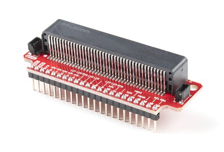
The micro:bit development boards themselves provide a wide range of possibilities for use in potential projects, offering built-in sensors, accelerometer, Bluetooth and more. For more advanced users looking to expand these basic capabilities, this SparkFun-produced adapter, which allows micro:bit modules to be connected to a contact board, is ideal. SparkFun Qwiic micro:bit Breakout in combination with BBC micro:bit expands the programming possibilities. The board provides access to more pins and allows connection to I2C and SPI buses. This version of the adapter comes with ready made connectors, so you don't have to worry about soldering anymore.
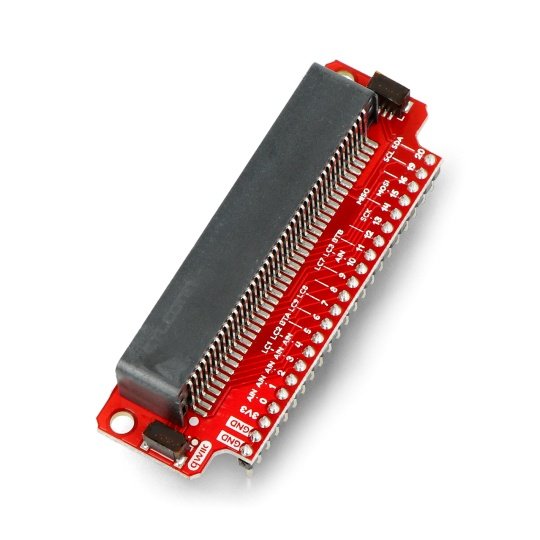
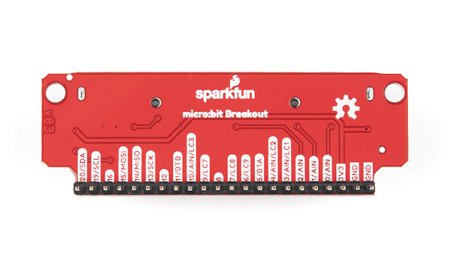
The micro:bit module itself has 3 I/O pins. Using the adapter you have access to all 21 pins as well as to ground and power pins on goldpin connectors (2,54 mm raster) which are compatible with contact boards.

SparkFun Qwiic micro:bit Breakout - contact board adapter for BBC micro:bit - with connectors.
Qwiic connection system
The sensor uses a convenient connection system Qwiicso there is no soldering required to connect it to the rest of the system. The SparkFun Qwiic Connect System is an ecosystem of sensors, actuators, shields, and I2C cables that make prototyping faster and less error-prone. All Qwiic-enabled peripherals use a common 4-pin JST connector with 1 mm spacing. This reduces the amount of PCB space required and avoids connection errors.
Table with description of pins
| Pin | Function 1 | Function 2 | Description |
|---|---|---|---|
| GND | System ground | ||
| GND | Chip ground | ||
| 3V3 | Power supply 3.3 V | ||
| 0 | Analogue input |
Connection to pin 0 |
|
| 1 | Analogue input |
Connection to pin 1 |
|
| 2 | Analogue input |
Connection to pin 2 |
|
| 3 | Input analogue | LED column 1 | LED control |
| 4 | Analog input | LED column 2 | LED control |
| 5 | Button A | Connection to push-button A on the micro:bit | |
| 6 | LED column 9 | LED control | |
| 7 | LED column 8 | LED control | |
| 8 | Open GPIO pin | ||
| 9 | LED column 7 | LED control | |
| 10 | Analog input | LED column 3 | LED control |
| 11 | Button B | Connection to push-button B on the micro:bit | |
| 12 | Open GPIO pin | ||
| 13 | SCK | SPI interface clock line | |
| 14 | MISO | GPIO / MISO line of SPI interface | |
| 15 | MOSI | GPIO / MOSI line of SPI interface | |
| 16 | Open GPIO pin | ||
| 19 | SCL | GPIO / I2C interface clock line | |
| 20 | SDA | GPIO / I2C interface data line |


