


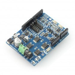


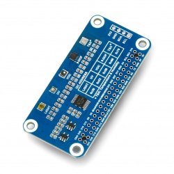


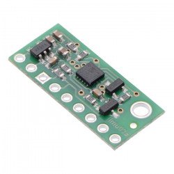


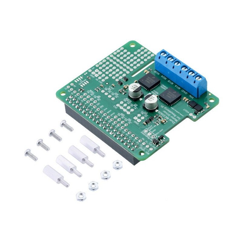


Module with dual MC33926 driver of motors, working with voltages from 5 V to 28 V and current up to 3 A per channel (max. 5 A). The shield can be linked directly with connectors of GPIO of minicomputer Raspberry Pi B+, A+ and 2.
|
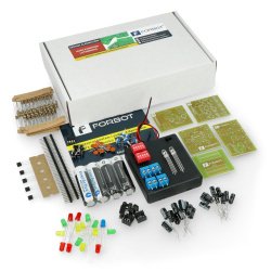
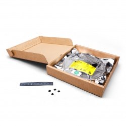
This version is up and ready to work. In our offer is also available as aKIT for self-assembly. |
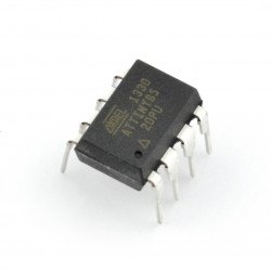
The module is based on a Freescale MC33926 and lets you control the motors with a supply voltage up to 28 V and a continuous current consumption of up to 3 A. The driver withstands seconds of jumping current up to 5 A. The speed of rotation can be controlled by the control signal of PWM.

In combination withthe Raspberry Pi, using a specially preparedlibraries,you can easily control the speed and direction of rotation of two DC motors. Form and pins of the board allow for direct connection to minicomputer, as shown in the pictures above. The system uses a 40-pin GPIO connector.
|
The product is compatible with Raspberry Pi B+ The manufacturer provides alibrary of Python for users of the Raspberry Pi. |
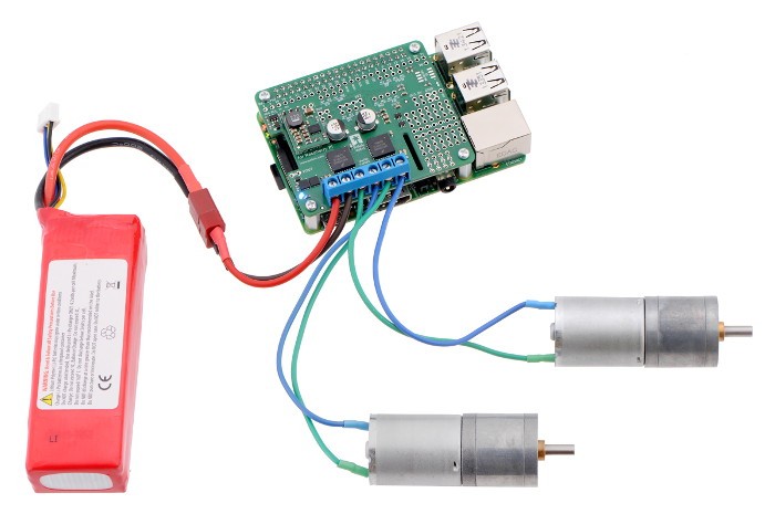
The power of the motors was separated from theRaspberry Pi B+. The voltage from the range of 5 Volts to 28 Volts should be connected to VIN and GND pins. Power of logic part of 3.3 V is consumed from minicomputer.

The following table shows which pins of the Raspberry Pi are used by driver of the motors:
|
Pin RPi GPIO |
Pin of the driver |
Description |
|---|---|---|
| 5 | Motor 1 SF |
Status pin. By default, in the high state. When an error of driver is detected, the driver switches to a low state. |
| 6 | Motor 2 SF |
Status pin. By default, in the high state. When an error of driver is detected, the driver switches to a low state. |
| 12 | Motor 1 PWM |
The PWM inputs to control the rotation speed of the motor. The maximum PWM frequency is 20 kHz. |
| 13 | Motor 2 PWM |
The PWM inputs to control the rotation speed of themotor. The maximum PWM frequency is 20 kHz. |
| 22 | Motor 1 EN |
By default, in the low state, it indicates the disabled outputs of the motors. To run the driver, you must specify the highstatus. |
| 23 | Motor 2 EN | By default, in the low state, it indicates the disabled outputs of the motors. To run the driver, you must specify the high status. |
| 24 | Motor 1 DIR |
Pin to choose the direction of rotation. In the low state, the current flows from output A to B. In high state - from B to A. |
| 25 | Motor 2 DIR | Pin to choose the direction of rotation. In the low state, the current flows from output A to B. In high state - from B to A. |
The table shows the operation modes depending on the zones:
| EN | DIR | PWM | MxA | MxB | Operation mode |
|---|---|---|---|---|---|
| 1 | 0 | PWM | PWM (H/L) | L | Forward rotation at a certain speed PWM %. |
| 1 | 1 | PWM | L | PWM (H/L) | Back rotationat a certain speed PWM %. |
| 1 | x | 0 | L |
L |
Braking (outputs connected to ground). |
| 0 | x | x | Z | Z | Disabled outputs. |
The remaining inputs and outputs are not connected to the Raspberry Pi, however, they are available directly from the module. Board sets some of the outputs to high or low status through the ways which should be stopped before you connect them to something else. The following table shows the default settings of the configuration of these pins.
|
Pin of driver |
Description | The default configuration |
|---|---|---|
| D1 |
Disabled input 1 (high state) |
By default, disabled (low state), connected via interruptible way. |
| D2 |
Disabled input 2 (low state) |
By default, disabled(highstate) connected via interruptibleway. |
| SLEW | The choice of rate of rotation |
By default, in high state - fast rotations, connected via interruptibleway. |
| INV | Inversion of inputs | Internally pulled to ground. |
| FB |
Feedback - output to measure the current |
Connected via a resistor and a low-pass filter, the sensitivity is approx. 360 mV/A. |
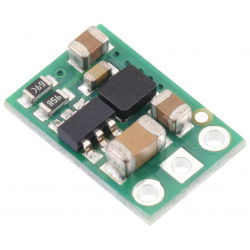
The device provides power to the minicomputer from the input voltage of module(VIN). To stabilize the voltage required forthe Raspberry Pi5 V, you can solderthe converter D24V10F5in specially prepared holes 5 V (output voltage), GND (ground), VOUT (supply voltage of motor).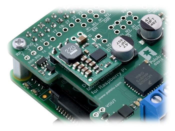
Useful links |
| Voltage to | 5.0 V |
| Voltage from | 28.0 V |
| Current | 4 A |
| Channels | 2 |
| Package width | 0 cm |
| Package weight | 0.029 kg |
Be the first to ask a question about this product!
Country of Origin: United States
Manufacturer Contact Details: Pololu Corporation 920 Pilot Rd. Las Vegas, NV 89119 USA [email protected]
EU Marketer Contact Details: BOTLAND B. DERKACZ SP. K. Gola 25A - 63-640 Bralin


