Description
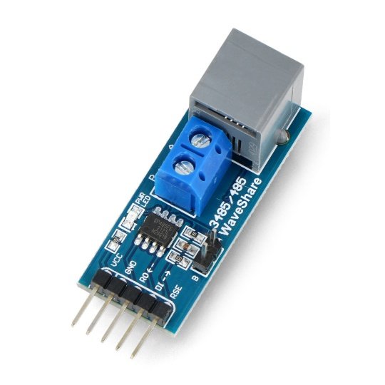
Converter allows you to connect the microcontroller via the RS-485 bus which supports up to 32 devices on a line length up to 1 km with a speed up to 10 Mbps.The module is based on a SP3485 fitted with connectors:goldpin, raster 2.54 mm- for connection with the microcontroller using the serial interfaceARK andRJ11for RS485.
Inputs
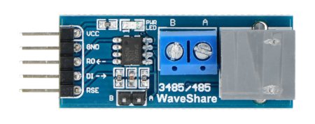
The module communicates via a serial UART interface usinggoldpin connectors - 2.54 mm raster. Description of the outputs is given in the table below.
| Pin |
Description |
|---|---|
| VCC | Power Supply: 3.3 V. |
| GND | The ground of the system. |
| RO | The output data on a serial bus must be connected to pin Rx of the microcontroller. |
| DI | The output data on a serial bus must be connected to pin TX of the microcontroller. |
| RSE |
Direction control outputs/inputs, RS485 bus:
|
| And | Output/ input RS-485 irreversable. |
| B | Output/ input RS-485 reversable. |
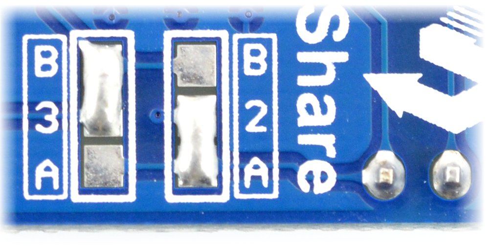
The system has three types of output connectors RS485:goldpin raster 2.54 mm,ARK (screw)andRJ11 (telephone). The location of the telephone connector can be configured by soldering jumpers signed on the reverse side of the module.
Jumper configuration on the back of the board.
Specification
- Working voltage: 3.3 V
- Driver: SP3485 (documentation)
- Communication with the microcontroller: serial interface UART
- Connectors RS485: goldpin 2.54 mm, SHEETS or RJ11
- Board sizes: 42 x 16.5 mm
Useful links |


