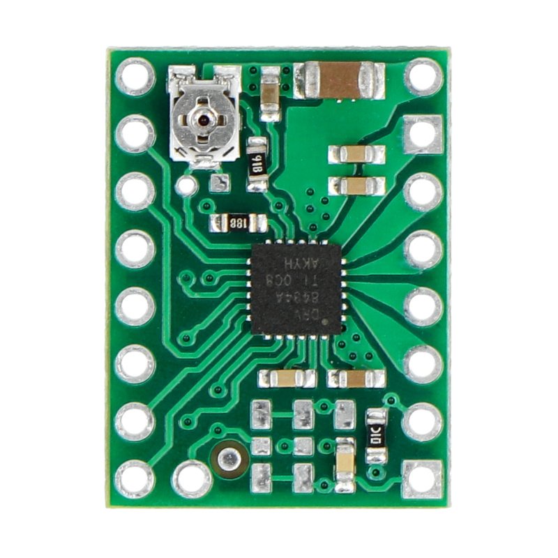


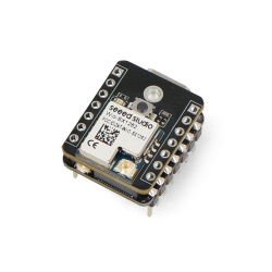


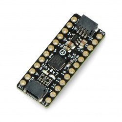

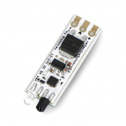

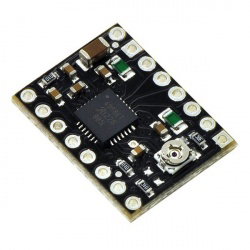


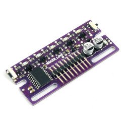


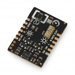


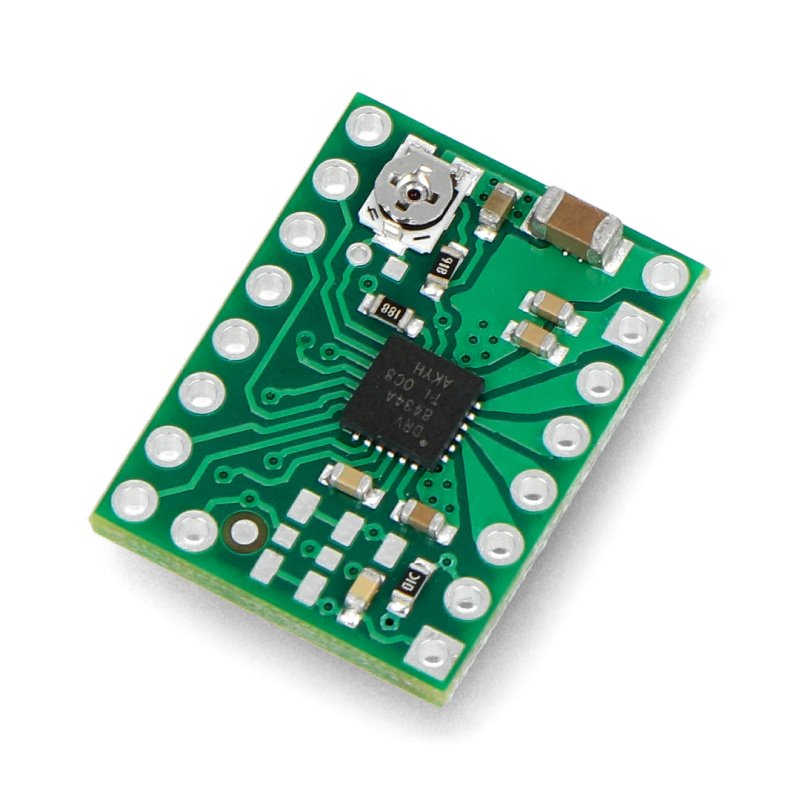


Stepper motor driver module based on the DRV8434A chip from Texas Instruments. It allows you to control a motor with a maximum current consumption of up to 2 A per coil, supplied with a voltage in the range from 4.5 V to 48 V. It offers a wide choice of step resolutions - from full to 1/256 step . Current regulation with a built-in potentiometer allows the use of voltages above the rated voltage of the motor to achieve higher stepping speeds . Thanks to the integrated voltage regulator , the user does not need to supply additional power to the logic part. The module is compatible in terms of size and pins with the system based on the A4988 driver, so it can be used as its replacement.
Our offer also includes drivers for stepper motors with different operating parameters.
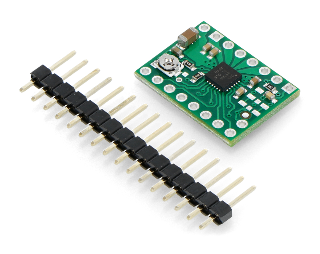
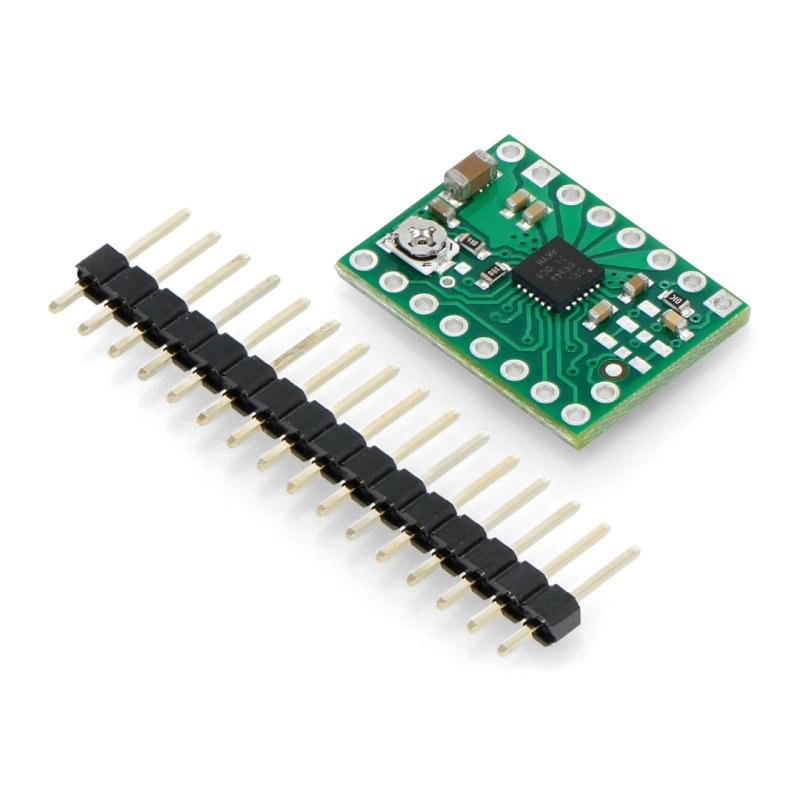
The set includes a goldpin strip.
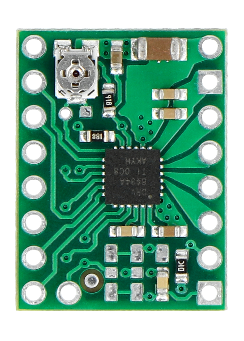
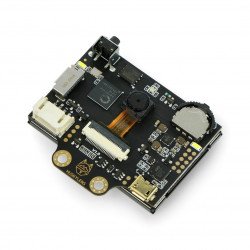
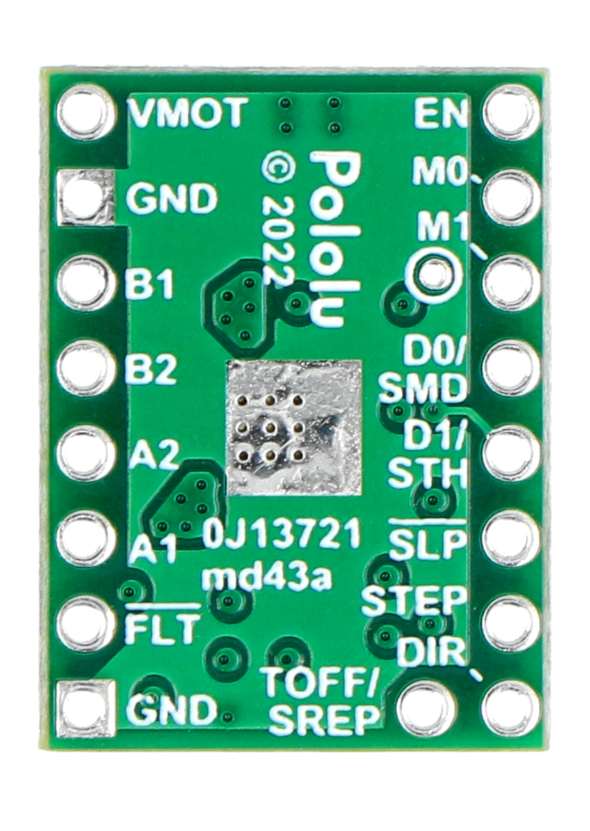
DRV8434A stepper motor driver 48 V 2 A - Pololu 3764.
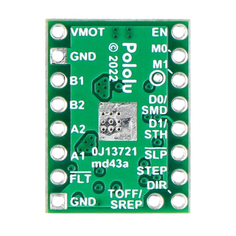
The controller requires a motor supply voltage of 4.5 V to 48 V, which must be connected via VIN and GND. Note that supply voltages below 6 V limit the maximum current limit that can be set.
One pulse given to the STEP pin corresponds to one step of the stepper motor in the direction given to the DIR pin. The STEP and DIR pins are internally pulled to ground (GND). Therefore, if the motor is only to rotate in one direction, DIR can be left unconnected.
The device has two different inputs for controlling power states: SLEEP (SLP) and ENABLE. Note that both pins are low by default. In order to start the controller, the SLP pin must be set to a high state.
The DRV8434A also has a FAULT (FLT) output. It goes low when it detects an abnormality in the system's operation. On the board, this pin has been connected to the SLEEP pin, so applying a high state to the SLP pin also pulls up the FLT to VCC. The DRV8434A chip includes a 1.5 kΩ safety resistor to connect the FAULT pin to VCC, making the driver compatible with the A4988 version.
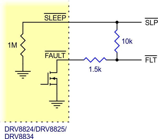
SLP and FLT pin diagram.
The step size is selected by inputs M0 and M1 . The method of obtaining the appropriate step resolution is shown in the table below.
| MODE0 | MODE1 | RESOLUTION |
| Low | Low | Full step with 100% current |
| high | 330kΩ to GND | Full step with 70% current |
| high | Low | Incomplete 1/2 step |
| Hi-Z | Low | 1/2 step |
| Low | high | 1/4 step |
| high | high | 1/8 step |
| Hi-Z | high | 1/16 step |
| Low | Hi-Z | 1/32 step |
| Hi-Z | 330kΩ to GND | 1/64 step |
| Hi-Z | Hi-Z | 1/128 step |
| high | Hi-Z | 1/256 step |
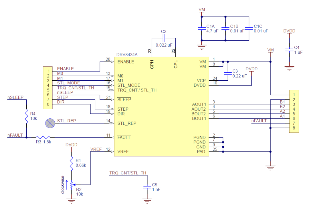
Module diagram.
To achieve high stepping speeds, motor power is typically higher than would be acceptable without active current limiting. For example, a typical stepper motor might have a maximum current rating of 1A with a coil resistance of 5Ω, which would indicate a maximum power supply of 5V to the motor. Using such a motor at 9V would allow higher stepping speeds, but the current must be limited to less than 1A to prevent engine damage.
The module allows for active current limitation using a potentiometer. One way to introduce a limitation is to set the controller to full step mode and measure the current flowing through one coil without giving a signal to the STEP input.
Another way is to measure the voltage on the VREF pin and calculate the current limit. The current limit can be calculated from the formula:
Current limit = VREF/ 1.32
The controller works in 11 modes, from full to 1/256 step.
Useful links
|
| Voltage to | 4.5 V |
| Voltage from | 48.0 V |
| Current | 1.2 A |
| Channels | 1 |
| Niebezpieczne | Component |
| Package width | 8 cm |
| Package height | 9 cm |
| Package depth | 1 cm |
| Package weight | 0.003 kg |
Be the first to ask a question about this product!
Product Information
The product is a component intended for further assembly/prototyping. It does not constitute a standalone finished product within the meaning of product safety regulations.
Dane GPSR
Country of Origin: United States
Manufacturer Contact Details: Pololu Corporation 920 Pilot Rd. Las Vegas, NV 89119 USA [email protected]
EU Marketer Contact Details: BOTLAND B. DERKACZ SP. K. Gola 25A - 63-640 Bralin