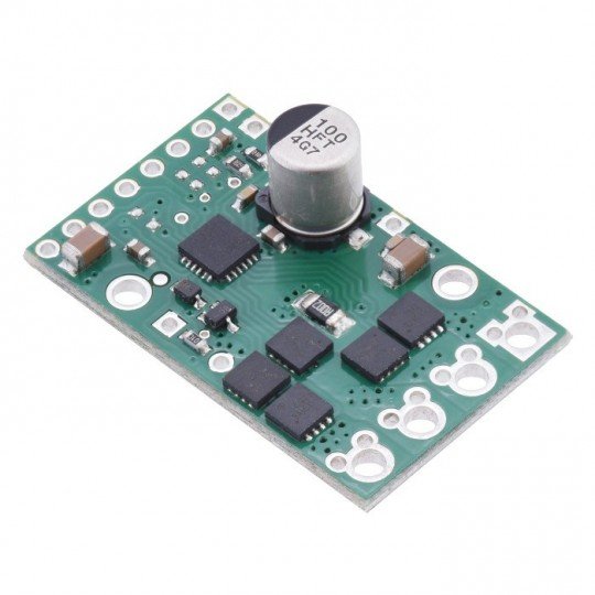
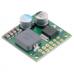
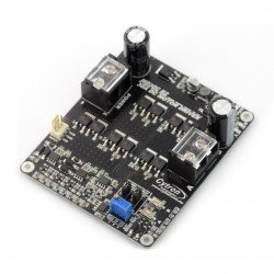
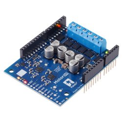
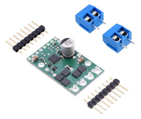
Product description: G2 High Power 18v17 - single channel motor controller 30 V / 17 A - Polol 2991.
The module allows to control one DC motor. The motor can be supplied with voltages from 6.5 to 30 volts with a continuous current consumption of up to 17 A, temporary (for 10 ms) up to 100 A. Speed can be controlled by PWM signal, direction by digital DIR output - giving low (logical 0) or high (logical 1) state. The device also has a current flow sensor and the possibility to limit the motor current.
Specification
- Number of channels: 1
- Power supply voltage: 6.5 V to 30 V
- Operating voltage of the logical part: 1.8 V to 5 V
- Continuous current: 17 A
- Maximum instantaneous current (up to 10 ms): 100 A
- PWM frequency: up to 100 kHz
- Current sensor sensitivity: 0.02 V/A
- Security:
- against reverse connection of the supply voltage
- against too low a supply voltage
- before a short circuit
- Dimensions: 33 x 20 mm
- Weight: 3.3 g (without connectors)
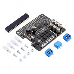
- Modules, goldpin and screw connections included
The set includes a controller and connectors for self-soldering.
Connection
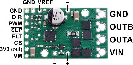
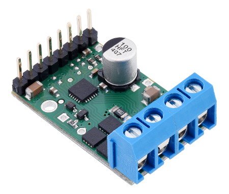
The motor connection and power supply are on one side of the module. The control pins (logical part from 1.8 V to 5 V) are located on the other side of the module. The motor power supply is capable of delivering high current. Gold or screw terminals (both included) can be soldered to the motor connectors.
To ensure high efficiency it is very important to connect a large capacitor between the motor power supply and ground as close to the module as possible. It is recommended to use a capacitor of at least several hundred μF. The required capacity depends on many factors, e.g. the quality and distance of the power supply (above 30 cm), motor parameters and PWM signal frequency. The capacitor can be connected to holes marked with "+" and "-". (VM and GND respectively). The controller has a built-in 100 μF capacitor sufficient for basic applications. However, for most systems a larger one is recommended.
The logical part of the module works with a voltage from 1.8 V to 5 V (maximum 5.5 V). By default, the controller is in a dormant state. To start it, the SLP pin must be connected to the high state. In typical applications, only two additional PWM and DIR pins are needed.
Queries
| PIN | Description |
|---|---|
|
VIN |
Motor supply voltage from 6.5 V to 40 V with reverse connection protection. |
| VM | The pin gives access to the motor power supply after protection against reverse connection. It can be used to supply energy from the reverse connection to other components. It should not be used with high current. Pin used as output. |
| + i - | Pins for capacitor connection connected to VM and GND respectively. |
| 3v3 | Adjustable 3.3V output providing several milliamps to power small components. Cannot be connected to other external power lines. Off when the controller is in sleep mode. Be careful not to short-circuit the V+ pin, as this may damage the board. |
| GND | The weight of the system. |
| OUTA | Motor output pin (connected to one of the motor terminals). |
| OUTB | Output pin for the motor (connected to the second motor terminal). |
| PWM | PWM input signal for motor control. Default is low. |
| DIR |
Pin direction of engine rotation. At low state, current flows from OUTA to OUTB, at high state OUTB to OUTA. Default is low state. |
| SLP | Pin setting the controller to sleep mode. The default is low (Sleep). |
| FLT | Error rate. Set to a low state when an error is detected. To be used, it must be connected to a high state (system logic voltage) |
| CS | Current sensitivity output. Generates voltage proportional to the motor current: 400 mV / A + 50 mV offset. |
| VREF | Reference voltage input. Connect the resistor to ground to limit the maximum output current. Without additional resistor the maximum value is 30 A. |
Truth table
The table shows the dependencies of the outputs on the input signals:
H - high state
L - low state
X - no matter
|
PWM |
DIR |
OUTA | OUTB | Engine condition |
|---|---|---|---|---|
|
H |
H | H | L |
The motor is clockwise at % PWM. |
|
H |
L | L | H |
The motor turns counterclockwise at % PWM. |
|
L |
X | L | L | Braking. |
PWM frequency
The controller supports PWM frequencies up to 100 kHz, but switching losses are proportional to the frequency. A 20 kHz frequency is used as standard.
The high PWM pulse length must be at least 0.5 μs to produce a change in the outputs, so low cycles become impossible at high frequencies. For example, for 100 kHz, the pulse duration is 10 μs and theminimum non-zero fill factor is 0,5 / 10 or 5 %.
Current measurement sensitivity
The CS output is only active when the H bridge is in controller mode. It is inactive (low state) when the controller is in braking mode, which happens when PWM is low or current limit is active. The current will continue to circulate through the motor when the controller starts braking, but the current on the CS pin will not reflect the motor current in braking mode. The CS voltage is used internally by the controller, to avoid interference, do not apply a capacitive load (capacitor) to this pin or connect it to a load over several mA.
The controller module has the ability to limit the motor current by cutting. When the current reaches the threshold value, the controller will set into braking mode for a short period of time before the motor is fed back on. It is more practical to use the controller with a motor that needs several amps during operation, but much more at start-up.
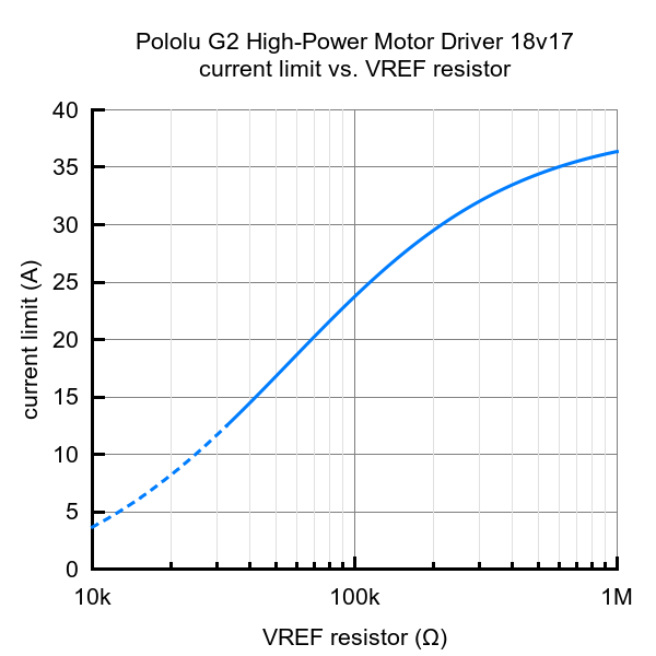
By default, the current limit is 30 A. It can be lowered by mounting a resistor between the VREF and GND pins. The following diagram shows the relationship between the resistor value at VREF and the current limit value. For example, for 100 kΩ between VREF and GND, the current is reduced to about 16 A. The current limitation is less accurate at particularly low settings (dashed line).
Error detection conditions
The controller can detect various errors signaled by setting the FLT pin to low. In order to use it, it must be connected to a high state (system logic voltage). Short circuit on the outputs, too low voltage and overheating can be detected. All errors disable the motor outputs but do not block them, this means that the controller will try to resume operation after the error has disappeared.
The controller can handle large current surges for a short time (100 A for several milliseconds). In continuous operation it can withstand 17 A, but this depends on external conditions such as ambient temperature and motor cooling. A heat sink can be added to the board to improve performance.
The controller has no automatic shutdown in case of overheating. Care must be taken to avoid damaging the system.
Video
Film describing the operation of the H-bridge - direct current motor controller.
List of G2 High Power controllers
| Name |
Voltage power supplies |
The current Continuous |
|---|---|---|
| G2 High-Power 18v25 | 30 V | 25 A |
| G2 High-Power 18v17 | 30 V | 17 A |
| G2 High-Power 24v21 | 40 V | 21 A |
| G2 High-Power 24v13 | 40 V | 13 A |
Useful links |
