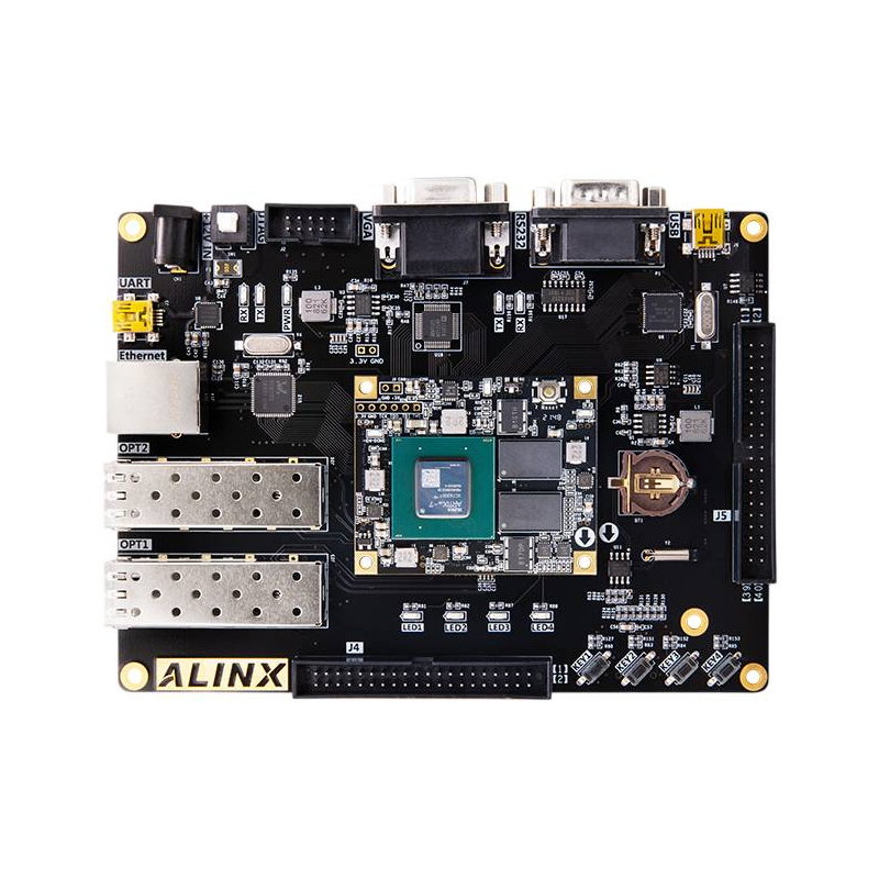





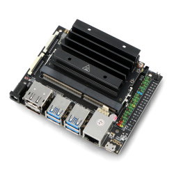
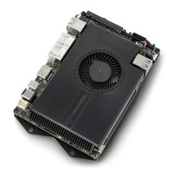




















The ALINX AX7202 is a powerful FPGA development board powered by the AMD Artix 7 XC7A200T , designed for communication, vision, and industrial projects. The kit offers 1 GB of DDR3 memory, 16 MB of QSPI Flash, Gigabit Ethernet, two SFP+ connectors, VGA output, USB 2.0, microSD, UART, and RS232 . Two 40-pin expansion connectors make it easy to connect cameras, displays, and measurement modules.
The ALINX AX7202 combines the AC7200 SoM with the AMD Artix 7 XC7A200T-2FBG484I processor and a carrier board equipped with a comprehensive set of interfaces. 1 GB DDR3 memory with a 32-bit interface supports large data streams, and 16 MB QSPI Flash provides configuration storage. Two SFP+ ports with up to 6.6 Gbps per lane and Gigabit Ethernet enable the creation of communication and networking devices. VGA output, a microSD port, USB 2.0, UART, and RS232 expand prototyping capabilities. Panasonic's modular design with four board-to-board connectors facilitates the development of custom FPGA- based devices, while buttons, LEDs, and expansion connectors support design testing and diagnostics.
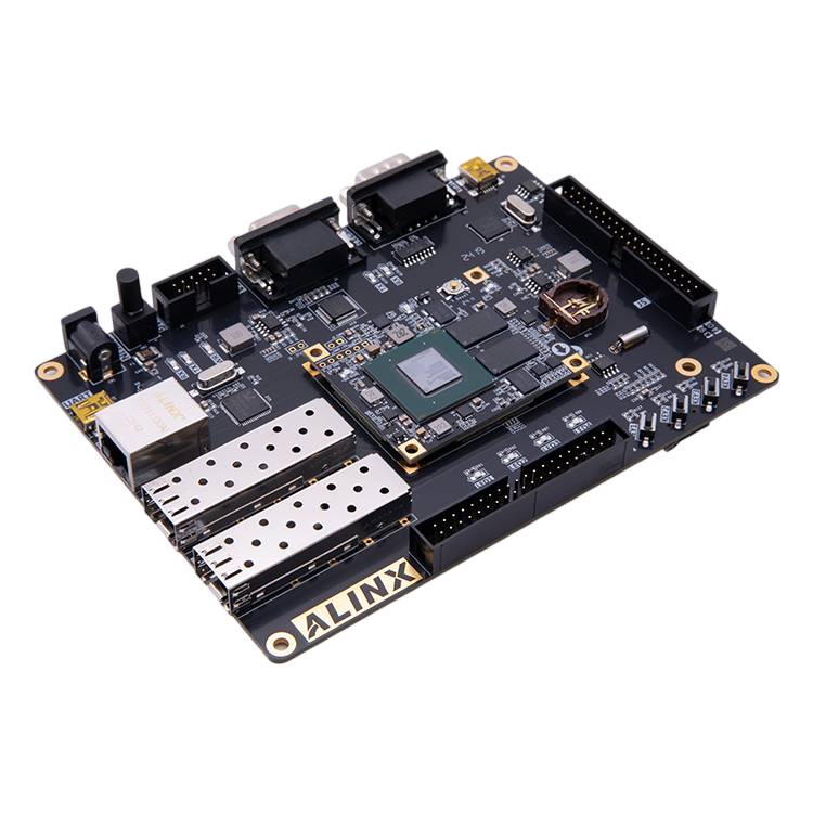
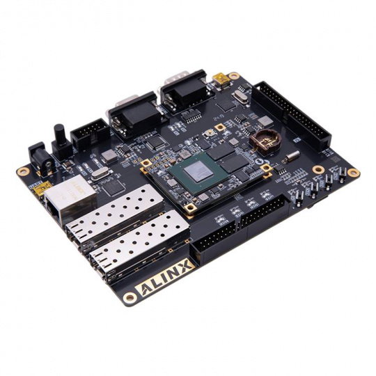
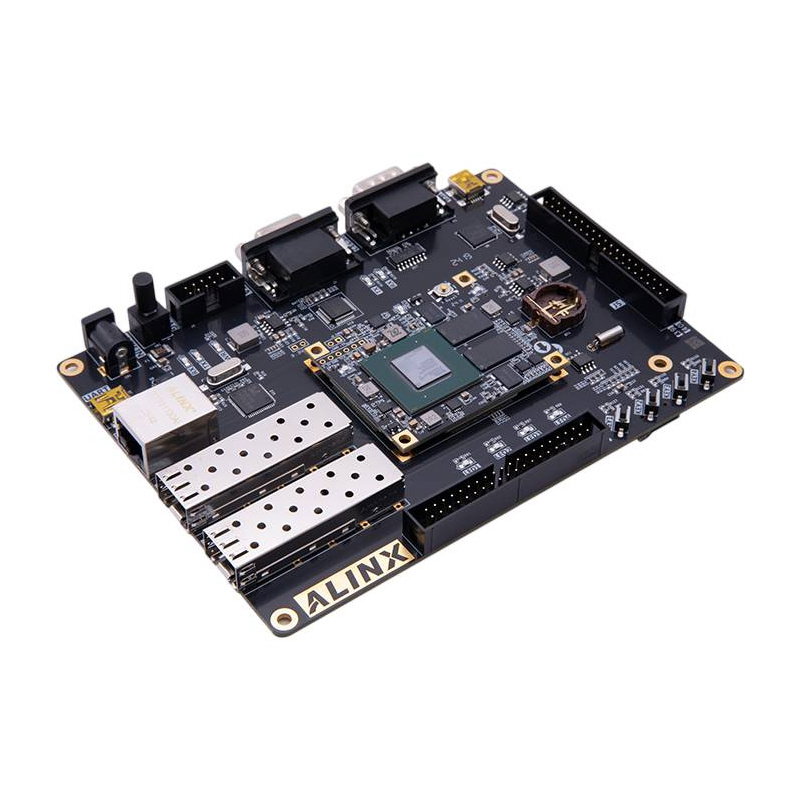
AX7202 - FPGA development board - AMD Artix 7 XC7A200T.
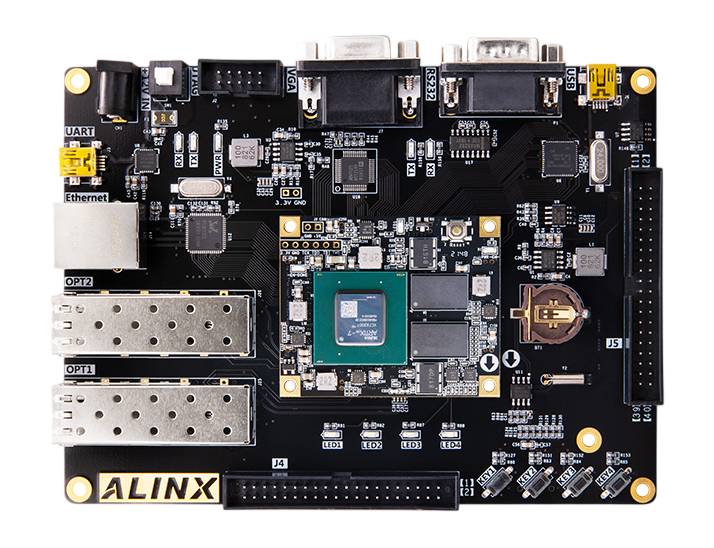
AX7202 FPGA development board equipped with AMD Artix 7 series.
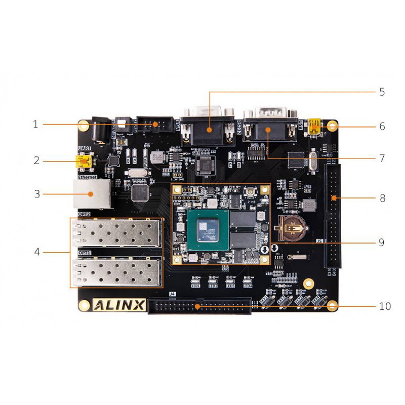
The AX7202 base board provides direct access to key communication interfaces, controls, and expansion connectors . The component layout simplifies connecting external devices and performing measurements during project startup. The list below corresponds to the main components labeled in the graphic.
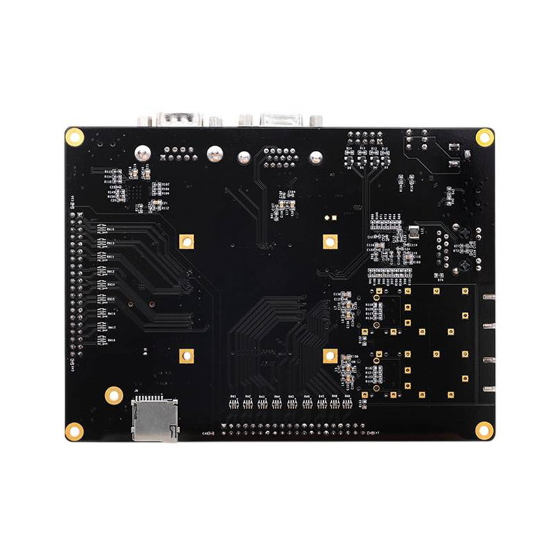
The board also includes a microSD card slot, a 24LC04 512-byte EEPROM, and a DS1302 real-time clock . These components enable storage of small configuration data, support for additional storage media, and time-dependent functions. This allows the AX7202 to serve as a standalone foundation for a more complex digital device.
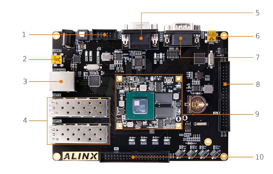
Arrangement of components on the board.
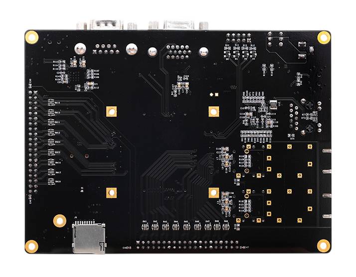
The AX7202 development board consists of an AC7200 SoM and a baseboard.
At the heart of the AC7200 module is the AMD Artix 7 XC7A200T FPGA , fabricated in 28nm technology and optimized for high performance with limited power consumption. It offers 215,360 logic cells, 740 DSP blocks, and approximately 13.14 MB of Block RAM , enabling the implementation of advanced projects in image processing, digital signals, and large data streams. The system's resources allow for the implementation of parallel hardware algorithms, communication controllers, MicroBlaze processors, and dedicated computational accelerators. Four GTP transceivers, working with two SFP+ connectors, provide transmission speeds of up to 6.6 Gb/s per lane . This configuration makes the AX7202 well-suited for prototyping high-speed communication, networking, and industrial systems.
| AX7202 Technical Specifications | |
|---|---|
| SoM module | AC7200 |
| FPGA family | AMD Artix 7 |
| FPGA chip | XC7A200T-2FBG484I |
| System manufacturing technology | 28 nm |
| Number of logical cells | 215360 |
| Number of DSP blocks | 740 |
| FPGA Block RAM memory | approximately 13.14 Mb |
| Number of GTP transceivers | 4 |
| Working memory | 1 GB DDR3 SDRAM |
| DDR3 bus width | 32 bits |
| Non-volatile memory | 16MB QSPI Flash |
| Ethernet | 1 x Gigabit Ethernet |
| Fiber optic interfaces | 2 x SFP+ |
| Maximum speed of a single SFP+ line | 6.6 Gb/s |
| Image output | 1 x VGA |
| USB | 1 x USB 2.0 |
| Serial interface | 1 x USB-UART |
| Industrial interface | 1 x RS232 |
| Memory card slot | 1 x microSD |
| EEPROM memory | 24LC04, 512 B |
| Real-time clock | DS1302 |
| Expansion connectors | 2 x 40-pin |
| Expansion connector raster | 2.54 mm |
| Number of I/O lines per expansion connector | 34 |
| User buttons | 4 |
| Programmable LEDs | 4 |
| Signal diodes | PWR, RXD and TXD |
| Supply voltage | 12V |
| Dimensions | 150 x 110 mm |
Useful links |
| Voltage to | 12.0 V |
| UC - Flash | 16 MB |
| UC - RAM | 1 GB |
| UC - Digital pins | 34 |
| UC - Ethernet | yes |
| UC - USB | 1x USB |
| UC - microSD | yes |
| UC - UART | yes |
| Niebezpieczne | Equipment |
| Package width | 21 cm |
| Package height | 19 cm |
| Package depth | 11 cm |
| Package weight | 1.036 kg |
Be the first to ask a question about this product!