


The servo is a closed-loop control system with feedback. It is the basic equipment of every remote-controlled mechanism, so it will certainly work well for all robots. Due to it, the control surfaces and components in the machine move. The servos are available in different sizes, and also differ in body shape and gear type. They are used in robotics, modeling and automation, where remote control is used. In this way we can control different physical processes that take place within the robot. In our shop there are servos with different working parameters, so you can use them in less and more advanced projects, adapting to its assumptions and own expectations and goals. In addition to servos, you will also find practical accessories such as branch cables in our shop. You will connect the servos and control them using Arduino minicomputer, which is also available in the offer of Botland.

Raspberry Pi 500+ Kit - US 16GB RAM 2,4GHz + official accessories
Index: RPI-27276
- Reduced price
- Sale

Servos
Loading...
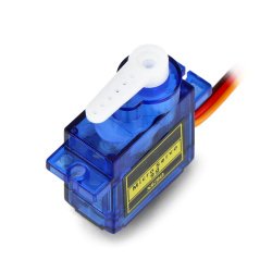
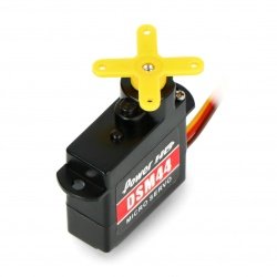
Micro servo.
Speed: 0.1 s/60 °.
Wait a minute: 1.8 kg*cm.
Dimensions: 22 x 12 x 27 mm.
Weight: 9 g.
Index: DNG-13128
Index: DNG-13128
Index: KAB-01387
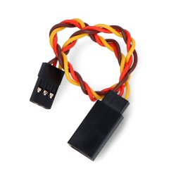
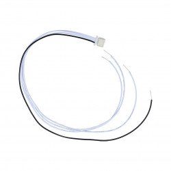
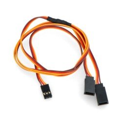
Extension cord for servos 15cm twisted
Extension cable with the length of 15 cm ended with the standard plug for the servos. It has twisted cables.
Index: KAB-01718
Index: KAB-01718
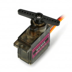
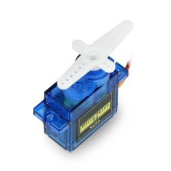
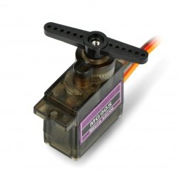
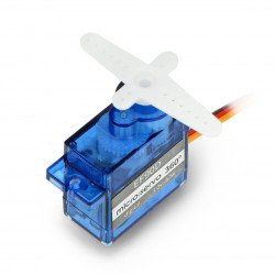
Servo MG-90S - micro - 180 degrees - metal gear
Microservo with a weight of 13.4 g. It features stable operation, accurate working angle and easy installation. It has a metal gearbox. Operating voltage ranges from 4.8 V to...
Index: DNG-20435
Index: DNG-20435

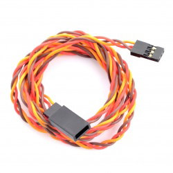
Extension cord for servos 45cm twisted
Extension cable with the length of 45 cm ended with the standard plug for the servos. It has twisted cables.
Index: KAB-01717
Index: KAB-01717
Index: KAB-00647
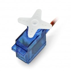
Servo MG-90S - micro - 180 degrees - plastic gear
Micro type servo with MG-90S designation. It has a gear made of plastic elements . The product is characterized by high stability and precision of operation. Supply voltage is...
Index: DNG-20436
Index: DNG-20436
Extension cord for servos 100 cm - twisted
This 100 cm extension cable terminates with a standard servo plug. It features twisted wires.
Index: KAB-08863
Index: KAB-08863
Servo Feetech FS90R - micro - continuous work 360 degrees
Feetech FS90R v2 micro servo. Operates as a variable speed motor. Powered from 4.8 V. Speed: 0.07 s/60°. Torque: 1.5 kg*cm. Dimensions: 30.5 x 12 x 22 mm....
Index: FTC-04689
Index: FTC-04689
Small, very fast servo type micro. Supply voltage: 4,8 - 6,0 V.
Speed: 0,07 sec/60 °.
Torque: 1,6 kg*cm.
Dimensions: 20,2 x 27 x 8.7 mm.
Weight: 6 gr.
Index: MOT-02853
Index: MOT-02853
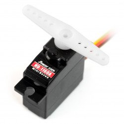
Servo PowerHD HD-1160A - medium
Popular servo type medium. Supply voltage: 4,8 - 6,0 V. Speed: 0,11 sec/60 ° . Torque: 2,7 kg*cm Dimensions: 29 x 12 x 30 mm Weight: 16 gr.
Index: MOT-02303
Index: MOT-02303
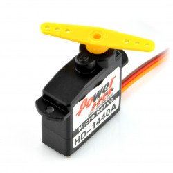
Servo PowerHD HD-1440A - micro
Small servo type micro. Supply voltage: 4,8 - 6,0 V. Speed: 0.10 sec/60 °. Torque: 0,8 kg*cm. Dimensions: 8.5 in. x 20,2 x 20,2 mm. Weight: 4.4 grams.
Index: MOT-02849
Index: MOT-02849
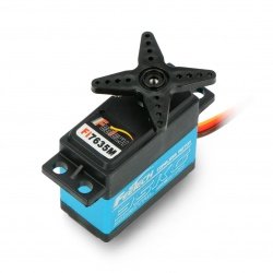
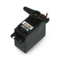
Servo Feetech FI7635M - standard
Standard type servo from Feetech, is powered by 6 V to 7.4 V . The no-load current consumption is 1150 mA . The range of motion of the servo is from 0° to 180°. It has a...
Index: FTC-17692
Index: FTC-17692
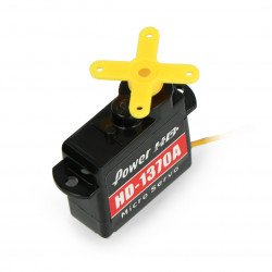
Servo PowerHD HD-1370A - micro
One of the smallest available in the world micro servos. Supply voltage: 4,8 - 6,0 V. Speed: 0.10 sec/60 °. Torque: 0,6 kg*cm. Dimensions: 20,2 x 8.5...
Index: MOT-02305
Index: MOT-02305
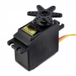
Servo type micro with durable karbonite gears.
Speed: 0.1 sec/60 ° .
Torque: 2.5 kg*cm.
Dimensions: 23 x 12 x 27 mm .
Weight: 9 g.
Index: MOT-01242
Index: MOT-01242
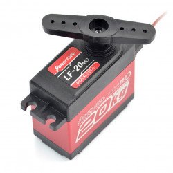
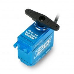
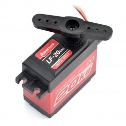
Servo PowerHD LF-20MG-360 standard - continuous rotation
Digital servo of standard type with aluminum gears and ball bearings. The power voltage from 4.8 V to 6.0 V Operates as a variable speed motor. Speed: 0.16 s./60°....
Index: MOT-08405
Index: MOT-08405
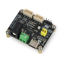
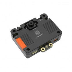
Bus Servo Adapter (A) - controller for ST/SC series serial bus servos - UART - Waveshare 25514
The Serial Bus Servo Adapter Board is a compact and versatile solution for powering and controlling ST and SC type servos. via UART and USB interface. It has a wide...
Index: WSR-24907
Index: WSR-24907
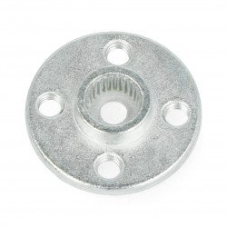
Round aluminum servo horn - 20mm / 6mm
Aluminum servo horn with a diameter of 20 mm and the mounting hole 6 mm. It is circular in shape. Works with standard servos. The set also includes mounting screws.
Index: GRL-12538
Index: GRL-12538

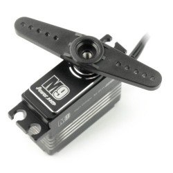
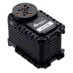
SC15 17kg Serial Bus Servo - UART servo - Waveshare 21568
SC15 17 kg Serial Bus Servo is a programmable high torque 17 kg * cm servo. It has a 180 ° rotation range in servo mode and a full 360 ° rotation range in motor mode. Any...
Index: WSR-21965
Index: WSR-21965
Servo PowerHD LF-20MG-270 standard
Digital standard servo with aluminum gears and ball bearings. The power voltage from 4.8 V to 6.0 V. Has a range of 270 °rotation. Speed: 0.16 s./60°. Torque:...
Index: MOT-08404
Index: MOT-08404
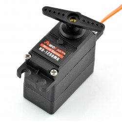
Servo PowerHD HD-1250MG - medium
Analog servo type medium. Speed: 0.12 seconds/60 ° . Torque: 3,5 kg*cm. Dimensions: 31,0 x 16,3 x 29.5 mm. Weight: 25 g.
Index: MOT-03600
Index: MOT-03600
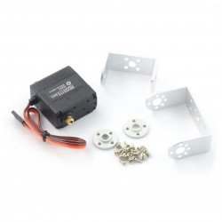
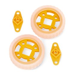
Servo EF90D 360 - micro - continuous work 360 degrees - with wheel and tire
EF90D Digital Servo Driver and Tyre. It has a 360° rotation angle and uses the pulse width to adjust the speed. The operating voltage is between 3 V and 5.5 V . The...
Index: EFS-17520
Index: EFS-17520
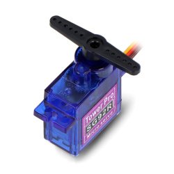
Servo TowerPro SG-5010 - standard
Servo of standard type, double bearing. Speed: 0.16 s /60 ° . Torque: 6.5 kg. Dimensions: 40 x 20 x 41 mm. Weight: 48 g.
Index: MOT-00485
Index: MOT-00485
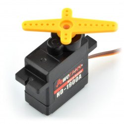
Servo PowerHD HD-1900A - micro
Servo type micro. Supply voltage: 4,8 - 6,0 V. Speed: 0,08 sec/60 °. Torque: 1,5 kg*cm. Dimensions: 22,9 x to 12.0 x 27.3 mm. Weight: 9 g.
Index: MOT-02851
Index: MOT-02851
Servomechanism - an extensive embodiment of an electric motor for controlling various physical processes
What is a servo (servomechanism)? Servos used in remotely controlled vehicles have standardized dimensions - from micro, through medium and standard, to mega size. Regardless of size, a typical servo design uses the feedback phenomenon, i.e., to a given control signal supplied to the servo, it must respond proportionally, in accordance with the expected result. The servo mechanism is connected to a potentiometer, on whose shaft the T-bar is mounted. Pushers are mounted on the T-bar, through which the drive from the servo is transferred to the target element controlled by it.
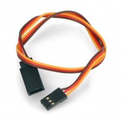
Connecting the servo - it's not that difficult!
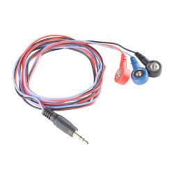
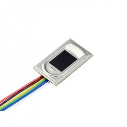
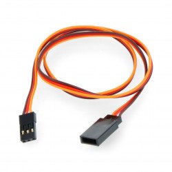
Most servos use a 3-pin female JST connector with a pin pitch of 2.54 mm. There are three wires connected to the connector - these are: a wire to ground (black or brown), a wire to the power supply positive (red) and a wire for the control signal (usually yellow). The insulation colors of individual servo wires may vary depending on the manufacturer's specifications, but the order in which the wires are placed in the connector is the same. If the length of the servo cable is insufficient, you can use extension cables with compatible connectors.
Servomechanism - Control
The third pin in the servo connector is used to provide a control signal that is intended to set the motor shaft to the desired position. The control signal has a square wave with variable duty cycle (PWM). The PWM signal frequency is standard and is 50 Hz, which means that a single signal period lasts 20 ms. The signal duty cycle in one period ranges from 1 ms to 2 ms. Applying a 1 ms pulse causes the servo shaft to rotate extremely counterclockwise, and for a 2 ms pulse, the servo rotates to the extreme counterclockwise position. In order for the servo shaft to return to the neutral position, a signal with a duty cycle of 1.5 ms must be given to the servo. One of the simplest ways to control a servo is to use one of the PWM hardware channels on the Arduino board. Arduino - servo control becomes very simple thanks to this minicomputer.
Power supply for servomechanisms
Servomechanism - principle of operation and power supply. In remotely controlled vehicles, batteries operate at a rated voltage of most often 4.8 V, and when using larger servos, it will be necessary to use 12.0 V batteries. However, for stationary applications, it will be optimal to use a power supply with an output voltage corresponding to requirements of the servo manufacturer. Regardless of the power supply method chosen, the servo motor draws an increased amount of current as the mechanical load increases. An incorrectly selected servo mechanism, due to providing insufficient torque, may increase energy losses in the power supply system and even contribute to incorrect operation of the controller. Thanks to the appropriate power supply and the Arduino minicomputer, the servo becomes a fully functional device for our projects.
Servos with a full range of rotation angle
A standard servo can rotate the shaft by a maximum of 90° to the left or right. For more complex applications, it is worth using servos with a rotation angle of 360°. Such servos can operate as a regular electric motor with a constant rotational speed. The maximum rotation speed of a servo with a full range of rotation angle is usually 60 rpm. If you need higher speeds for your application, then a better solution would be to use a regular DC electric motor, but for precision tasks it is best to use a stepper motor. Unlike conventional servos, 360° servos are equipped with a small potentiometer that allows the servo to be calibrated to the control signal. For servos with a full range of rotation angle, a pulse with a duty cycle of 1.5 ms will stop the servo motor, and pulses with a longer or shorter duration will cause the servo shaft to rotate clockwise or counterclockwise, respectively.
Servomechanisms - FAQ
Three key attributes help you choose a servo: continuous torque, which is the time-weighted average of torque over a complete cycle, peak torque - the highest torque required at any point in the cycle, and speed, expressed in revolutions per minute.
It depends on the type of servo. It can be assumed that servomechanisms consist of a DC motor, a rotary potentiometer , a gear, an electronic control system for positioning the motor shaft and a housing.
The intelligent circuit together with the potentiometer causes the servo to rotate as indicated. The gear mechanism adopts the high input speed of the motor (fast), and the output obtains an output speed that is slower than the original input speed, but is more practical and has wider application.