









On Sale










RGB LED
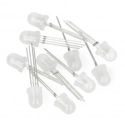
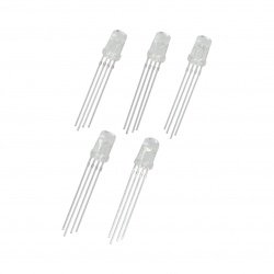
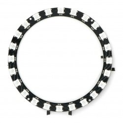
Every project should contain an LED diode, and the best solution is a tricolor one! By mixing the colors, for example with a PWM output from a microcontroller, you can get any range of actual colors. An RGB LED is an LED that can light up in three different colors at the same time (red, green, and blue). By letting the base colors light up with different intensities, an RGB LED can light up in many different colors. When it shines at full strength in all colors, the light turns white. When it only glows red, the light also turns red. When it glows both red and green, the light turns yellow. If you want to buy an RGB LED for your project, visit Botland.store. We offer a large selection of high-quality RGB LEDs, and we can assure you that our products will meet your expectations. In this category, you will find items such as LED RGB rings, LED modules for PCB, LED chains, and many more! We provide the best prices and fast delivery.
Products
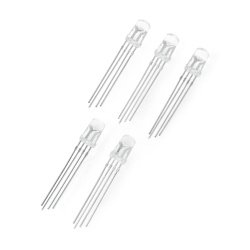


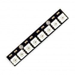
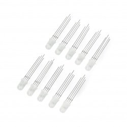
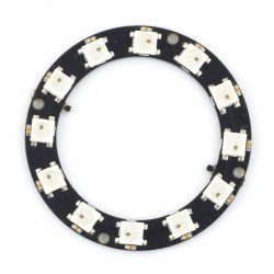


See also
RGB diodes shining in any color
The color of an LED's emission depends on its structure, and more precisely, on the semiconductor material from which its PN junction is made. The energy of the photon emitted from the light-emitting diode is determined by the energy gap of the material - this translates into the wavelength of the photon, i.e. its color. As the energy gap in the finished diode cannot be changed, RGB diodes are used to control the color of the emitted light - in a single structure, the system has three diodes - Red, Green and Blue. The RGB color model is an additive model in which red, green, and blue light can be added together to reproduce a wide range of colors.
Controlling RGB LEDs - PWM signal
Light-emitting diodes are controlled by a current signal - it is the current flow, not the applied voltage, that causes the electroluminescence of the PN junctions in the LED. While current stabilization is simple, digital control is more complex. Therefore, PWM controllers are used to control the brightness of LEDs instead of digitally regulated current sources. Such systems modulate the current flowing through the diode with a square wave signal with variable duty cycle. By regulating the percentage of time the LED is on, the brightness is regulated - the LED is turned on and off so quickly that human eyes do not notice the blinking, but only the average emission intensity at a given moment.
Addressable RGB LEDs with built-in drivers
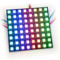
RGB LEDs with an integrated controller are an intelligent light source that can be digitally controlled. In addition to three LEDs, an addressable three-channel LED controller is also integrated in a single element. It has a digital input that allows you to transmit data and control the relative brightness of each of the integrated LEDs. Moreover, these elements can be cascaded together. Each driver has a 24-bit shift buffer that controls the brightness of each LED (eight bits per LED). Subsequent data transferred to the element via the serial interface is sent to the next diode using only one GPIO line, e.g. a microcontroller or a single-board computer.
RGB LEDs - FAQ
The RGB diode is nothing more than a combination of three LED structures (red - R ed, green - G reen and blue - B lue) within one housing. RGB LEDs come in various varieties, including through-hole (THT) and surface-mount (SMD) diodes, and as elements of larger LED modules.
Depending on the design, the anodes or cathodes of all three "component diodes" are connected together and led outside the housing (we are then talking about a diode with a common anode or a common cathode, respectively). The anode (or anodes) should be connected to a higher potential (e.g. the positive pole of the battery), and the cathode (or cathodes) should be connected to a lower potential. Please remember that each of the "channel" terminals (R, G, B) should be powered by a series current-limiting resistor .